


At this point, your spindle system should already be physically installed, wired for power, and tested successfully in manual mode. If you have not completed that yet, stop here and finish Phase 1 and Phase 2 first.
Manual mode is the foundation of the spindle system installation process. It confirms that the spindle, enclosure, and core power connections are all working correctly before you move into controller integration. Once that is verified, the next step is connecting the control cable between your CNC controller and the VFD enclosure so your controller can later command spindle speed automatically.
Unlike spindle kits, spindle systems do not require opening the VFD and landing wires on internal terminals. Instead, the enclosure provides dedicated external ports on the left side for controller wiring and accessories.
What this phase covers
This article explains how to connect the spindle system’s controller control cable to the correct port on the left side of the VFD enclosure.
This page covers only:
-
PWM control connection
-
Modbus / RS-485 control connection
This page does not cover:
-
the RUN relay port
-
the IoT barrel plug port
-
controller-specific wiring on the machine side
-
software setup or testing
Those items are handled in separate KB articles.
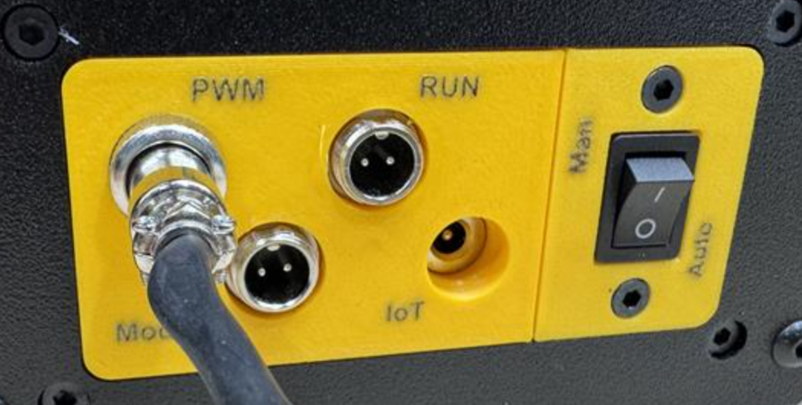
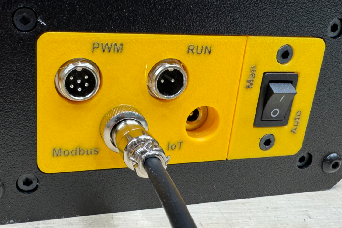
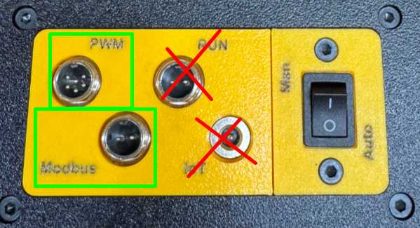
Understanding the left-side ports
On the left side of the VFD enclosure, there are several different ports. It is important to use the correct one.
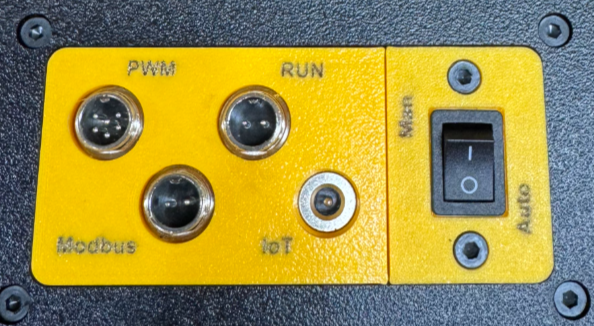
The spindle system manual identifies the following left-side connections on the enclosure:
-
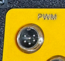
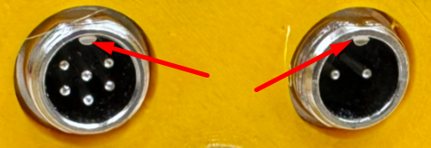
GX12-6 Pin (PWM), commonly used for most controllers
-
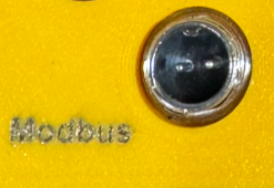
GX12-2 Pin (Modbus), commonly used for certain controllers such as Onefinity Black Box style systems
-
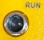
GX12-2 Pin (Run), labeled for the VFD’s internal relay output
-
MOS switch housing
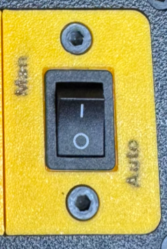
-
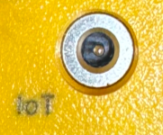
IoT strip inlet for the optional IoT power strip accessory
Because these ports are physically close together, customers should take a moment to identify them before plugging anything in.
Important: Do not confuse the ports
Two of the ports on the left side use 2-pin GX12 connectors:
-
the Modbus / RS-485 port
-
the RUN relay port
These are not the same thing.
The Modbus port is used for controller communication.
The RUN port is tied to the VFD’s internal relay and is not the controller communication port. It should not be used in place of the Modbus port.
Likewise, the IoT barrel plug is also separate and is used for the optional IoT power strip function, not for controller communication. The IoT power strip inlet is used to trigger external AC devices such as a shop vac, pond pump, or chiller, we'll discuss this in a separate kb article.
Understanding the two control methods
Your spindle system will use one of two control methods, depending on the CNC controller selected when the system was ordered:
Option 1: PWM
PWM is the most common automatic spindle control method. In this setup, the controller sends a voltage-based speed signal to the VFD. This signal may be 0 to 5V or 0 to 10V, depending on the controller, and the VFD converts that signal into spindle RPM.
Option 2: Modbus / RS-485
Modbus is a two-wire communication method that provides direct communication between the controller and the VFD. Modbus is less common, but offers two-way communication and closer tracking to commanded RPM than PWM.
Your system was pre-configured based on the machine or controller selected at the time of purchase. The automatic control method depends on the CNC controller capability you told PwnCNC you had when ordering.
Step 1: Identify which control cable you have
Before plugging anything in, identify your control cable if you purchased one.
PWM control cable
If your spindle system uses PWM, your control cable will plug into the GX12-6 Pin PWM port on the left side of the enclosure.
Modbus control cable
If your spindle system uses Modbus / RS-485, your control cable will plug into the GX12-2 Pin Modbus port on the left side of the enclosure.
Step 2: Connect the control cable to the correct port
Once you know which control method your system uses, connect the cable to the matching port on the left side of the enclosure.
If your system uses PWM
Plug the control cable into the:
-
GX12-6 Pin PWM port
This is the port used for most PWM-based CNC controllers.
If your system uses Modbus / RS-485
Plug the control cable into the:
-
GX12-2 Pin Modbus port
This is the communication port used for compatible Modbus-based controllers.
Connector alignment note
These GX12 connectors have an alignment notch, so they only insert one way. Do not force the connection. Align the connector properly, insert it fully, and tighten the retaining collar.
Step 3: Do not use the RUN port for controller communication
It is worth repeating because this is an easy mistake to make:
The RUN port is not the Modbus port.
Even though both the RUN port and Modbus port use 2-pin GX12 connectors, they serve different purposes.
For this phase, only use:
-
the 6-pin PWM port, or
-
the 2-pin Modbus port
Do not plug the controller communication cable into:
-
the RUN port
-
or the IoT barrel plug
What about the RUN port and IoT port?
The spindle system includes additional left-side connections for expanded functionality, but they are not part of the main controller wiring step.
RUN port
The RUN port connects to the VFD’s internal relay. This is a separate function and will be covered in its own KB article.
IoT barrel plug
The IoT barrel plug allows the VFD to trigger an external AC device when spindle RPM rises above the activation threshold. This is commonly used for things like:
-
a shop vac
-
a pond pump
-
a chiller
It also notes that the trigger point is about 5500 RPM.
Those accessory functions are covered separately and are not part of this article.
Step 4: Continue to your controller-specific guide
Once the correct control cable is plugged into the correct enclosure port, the next step is connecting the other end of that cable to your CNC controller.
That part is machine-specific and should be completed using the controller-specific KB article for your machine or controller.
Use the guide below that matches your CNC machine and controller.
PWM Controller Guides
-
Genmitsu Controllers
Modbus / RS-485 Controller Guides
-
BuildBotics (branded) Controllers
-
Sienci Labs - SuperLongBoard(-ext) Controllers (aka AltMill's)

