


At this point, your spindle kit should already be physically installed, wired for power, and tested successfully in manual mode. If you have not completed that yet, stop here and finish Phase 1 and Phase 2 first.
Manual mode is the foundation of the spindle kit installation process. It allows you to confirm that the spindle, VFD, and high-power wiring are all working correctly before adding controller integration. Once that is verified, the next step is to install the low-voltage control wiring that will eventually allow your CNC controller to command spindle start, stop, and speed automatically.
Important: This phase does not enable automatic control... yet
Our spindle kits ship with the VFD configured for manual operation first. That is intentional.
By shipping the VFD in manual mode, customers can:
-
complete the physical installation first,
-
verify the spindle powers on and runs correctly,
-
and achieve a successful early milestone before moving into the more complicated controller integration phases.
Because of that, completing the controller wiring in this phase does not immediately hand control over to the CNC controller.
This phase only prepares the wiring needed for automatic operation.
After the wiring is complete, you will continue to the next phase, where you will update the required VFD settings to switch the system from manual-mode-only operation to automatic-mode-only controller control.
For spindle kits, this is a one or other situation. You can only control the vfd/spindle in manual-mode OR automatic-mode.
What this phase covers
This article covers the controller wiring portion of the spindle kit installation.
To make this easier, we recommend breaking this phase into two stages:
Stage 1: Wire the VFD side
In this stage, you will connect the control cable to the correct control terminals inside the VFD.
Stage 2: Wire the controller side
In this stage, you will connect the other end of that control cable to your CNC controller using the controller-specific article for your machine or controller.
This two-stage approach keeps the process organized. The VFD side is very consistent, while the controller side varies depending on the make and model of the CNC machine or controller.
Understanding the two control methods
Don't do any wiring just yet... just have the wire ready as we need to cover some basic spindle control functionality.
There are two common ways a CNC controller can communicate with the VFD:
Option 1: Modbus / RS-485
Some CNC controllers communicate with the VFD using Modbus, also called RS-485 communication.
This method uses a two-wire communication connection between the controller and the VFD.
On the VFD side, this is very simple:
-
SG(+)
-
SG(-)
If your controller uses Modbus, the control cable will be wired into these two terminals inside the VFD.
Option 2: PWM control
Other CNC controllers use PWM-based spindle control. Depending on the controller, this may be a simple analog speed signal only, or it may also include one or more relay-based run commands.
At minimum, a PWM-based controller usually provides:
-
a speed signal
-
and signal ground
On the VFD side, the minimum PWM wiring is:
-
VF1 = PWM / analog speed signal
-
GND = signal ground
Some controllers can also provide relay-based directional run commands. These connect to the digital input terminals on the VFD:
-
DI1 = Forward / CW
-
DI2 = Reverse / CCW
-
COM = Digital common
By default:
-
DI1 is programmed for Forward / CW
-
DI2 is programmed for Reverse / CCW
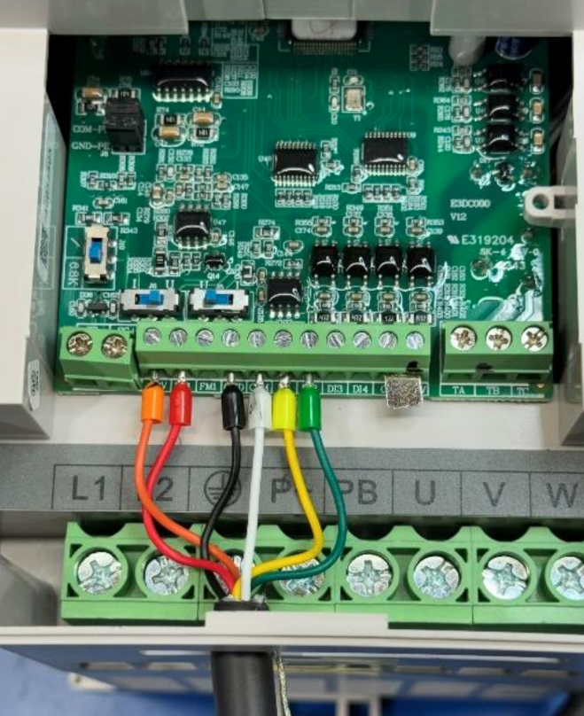
We recommend wiring the PWM control cable as shown in the following image:
Not every controller supports all of these functions. Some controllers only provide a PWM speed signal. Some can also trigger forward run. Some can trigger both forward and reverse.
Your controller-specific article will explain what your machine supports.
Stage 1 - Wire the VFD Side
Before wiring anything, make sure the VFD is powered off and unplugged from AC Power.
The first step in controller wiring is to connect the control cable inside the VFD. The exact terminals used depend on whether your controller uses Modbus or PWM.
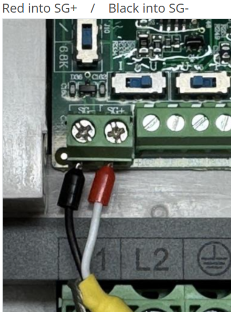
If your controller uses Modbus / RS-485
your control cable will have 2-conductors and should be wired as follows:
-
SG(+) = (Red wire)
-
SG(-) = (Black wire)
That is all that is required on the VFD side for Modbus communication.
If your controller uses PWM
your control cable should have 6-conductors and should be wired as follows:
-
VF1 = (Red wire) PWM / analog speed signal
-
GND = (Black wire) signal ground
-
DI1 = (Yellow wire) Forward / CW
-
DI2 = (Green wire) Reverse / CCW
-
COM = (White wire) Digital common
Side Note: How the digital inputs work
The DI terminals are digital input terminals. They are used to trigger programmed VFD functions.
For spindle kits:
-
DI1 is programmed for Forward / CW
-
DI2 is programmed for Reverse / CCW
The COM terminal is the shared digital common used with these digital input terminals.
When a compatible controller closes the relay between one of these digital inputs and COM, it triggers the programmed function for that input.
In simple terms:
-
DI1 + COM triggers forward/CW spindle rotation
-
DI2 + COM triggers reverse/CCW spindle rotation
Stage 2 - Wire the Controller Side
Once the VFD side wiring is complete, the next step is wiring the other end of the control cable to your CNC controller.
This part is controller-specific.
Different machines and controllers use different:
-
terminals,
-
plugs,
-
pinouts,
-
signal types,
-
voltage ranges,
-
and software settings.
Because of that, Stage 2 should always be completed using the KB article that matches your exact machine and controller.
Choose Your Controller Guide
Use the guide below that matches your CNC machine and controller.
PWM Controller Guides
-
Genmitsu Controllers
Modbus / RS-485 Controller Guides
-
BuildBotics (branded) Controllers
-
Sienci Labs - SuperLongBoard(-ext) Controllers (aka AltMill's)

