


This article explains how to configure MASSO for an ISO20 ATC setup that uses tool forks instead of tool cups.
Tool cups and tool forks both hold ISO20 tool holders, but MASSO needs to move differently for each style. With tool cups, the tool holder is usually picked up and dropped off vertically. With tool forks, the spindle typically slides the ISO20 holder into the fork, releases the drawbar, then moves up then slides away from the fork before moving to the next tool.
This article will cover the orientation where your tools are lined along the back of your machine.
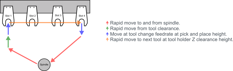
For MASSO, this is configured as a Linear Tool Changer Type 2.
MASSO’s original documentation is available here if you want to deep dive:
Before You Start
Before programming the fork positions, make sure the mechanical side is solid:
- The forks are mounted securely and cannot move during a tool change.
- The ISO20 holder sits fully and consistently in each fork.
- The spindle can approach the fork without the nut, tool, dust boot, or spindle body hitting anything.
- Your drawbar clamp/unclamp is already working from MASSO.
- Your “tool in spindle” sensor is working correctly.
- Your machine has been homed before recording any tool fork positions.
Important: All tool changer coordinates are machine coordinates, not work coordinates. Always home the machine first before recording or testing positions.
Here are several other considerations:
1. For extra precaution, unload your ISO20 tool holders of their bit, collet, and nut. This way missteps don't result in broken bits.
2. Before you begin empty all tool-forks since your first task is to record their physical X, Y, and Z machine coordinates.
3. Be sure your machine is properly homed as all coordinates are recorded/configured based on Machine Coordinates.
4. Jogging the machine around in Continuous is fine at first, but be sure to switch to steps so you can very carefully move your spindle as needed.
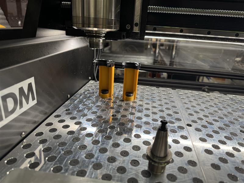
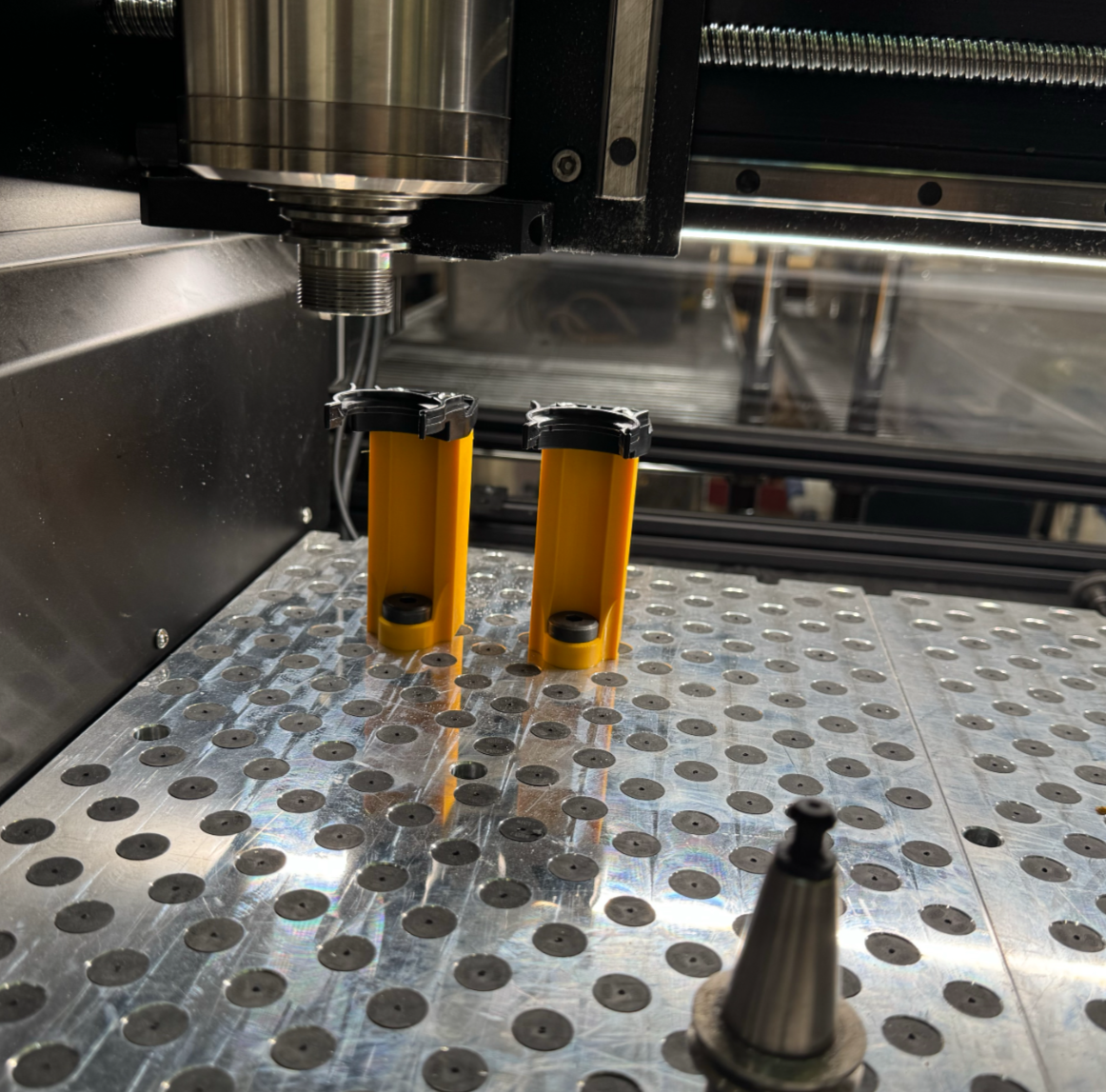
In the photo above you'll see the two tool-forks are empty, no bits/collets/nuts are attached to my ISO20 tool holders and i'm ready to start capturing their physical location on the homed machine.
Step 1: Jog and Capture Tool Fork Coordinates
Capture Z Coordinate First
Jog your machine to immediately in front of the fork you're labeling as Slot-1
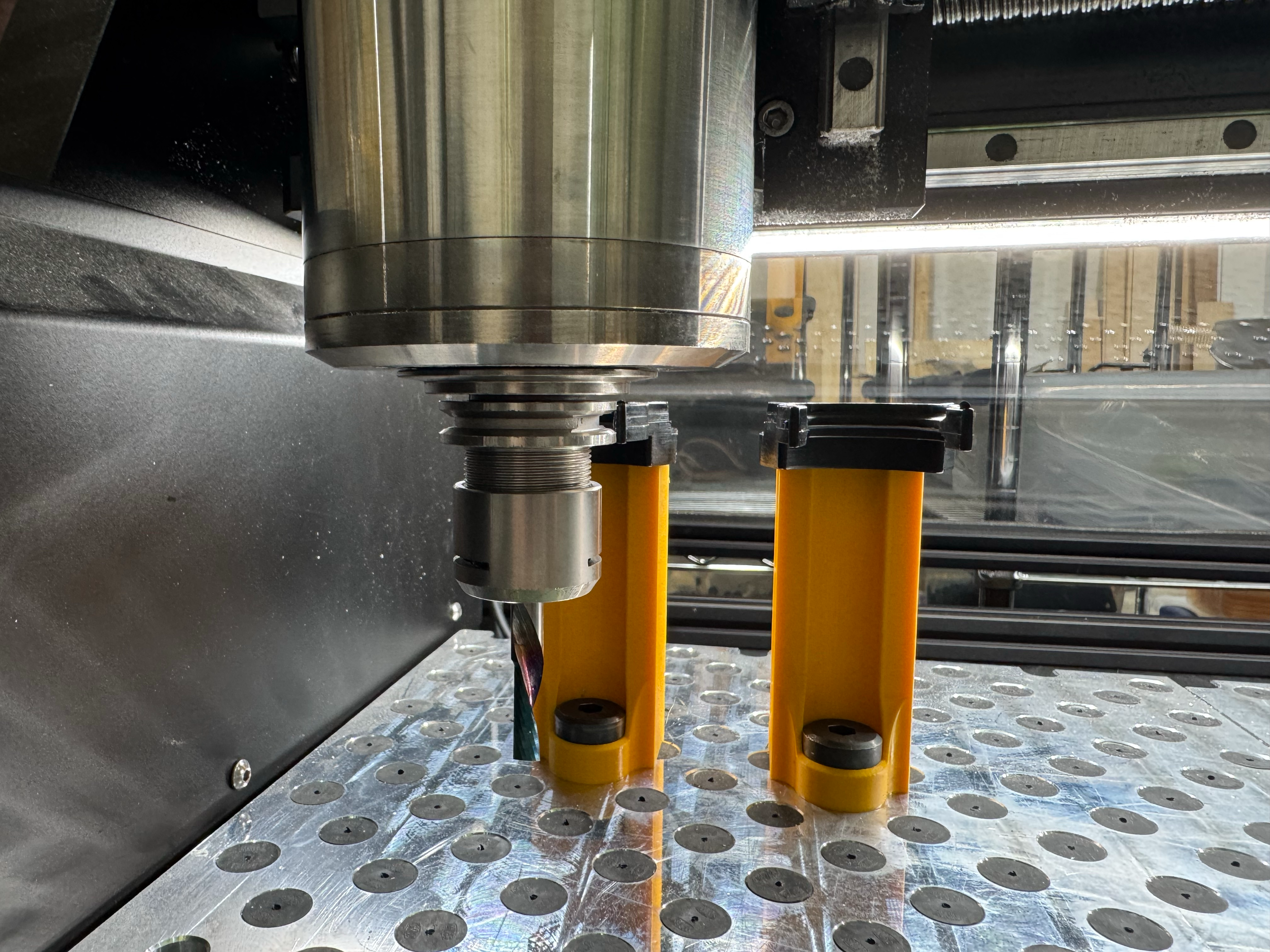
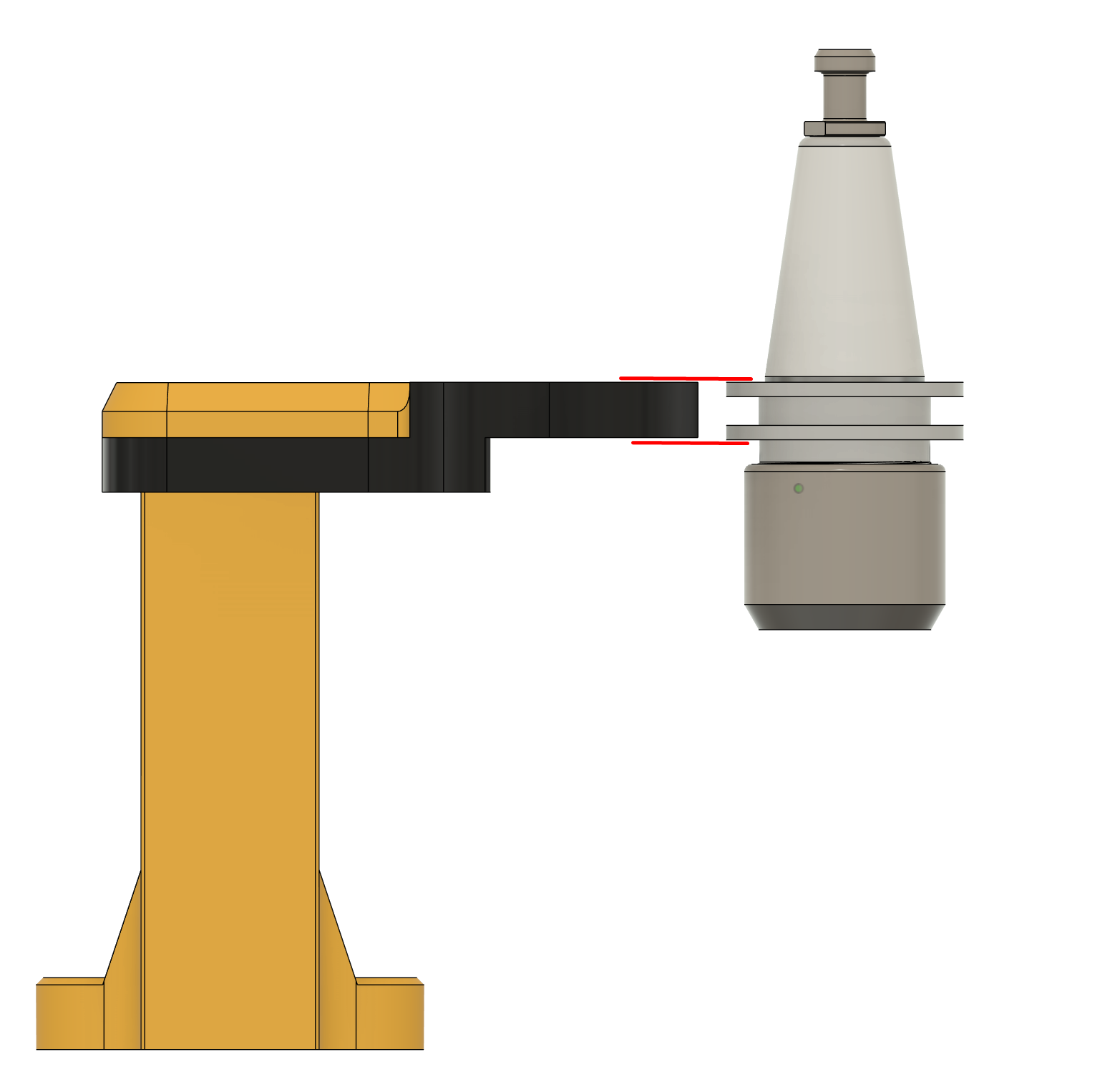
Your first value to capture is the Z height of your forks. All forks must be the same z-height so jog your carriage so the ISO20 tool holder in your spindle motor is positioned vertically right in front of the first fork. Then record the Machine Coordinates Z height.
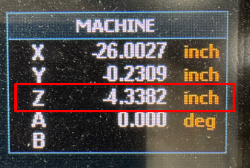
Save this value for later. I like to take a photo of this box, otherwise write it down. Be careful to capture the negative sign if it is present.
Pick & place Z position = Z
Capture X Coordinate of Slot-1 then Repeat for Every Slot
Next you'll want to focus on the X position of your forks, but first you'll need to jog the machine back in Y slowly and adjust the X position as needed to align the first forks till they both gently touch the iso20.
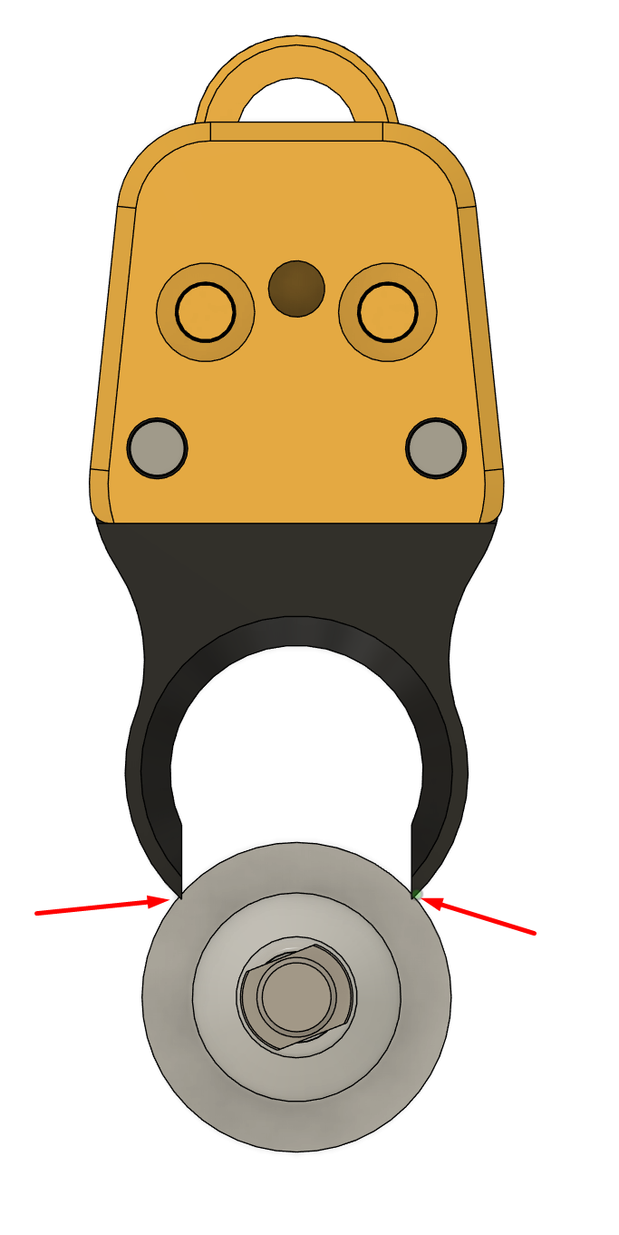
You'll want to do this before you continue moving back. You can place your fingers on either side, when not moving, to confirm the X coordinate then capture.
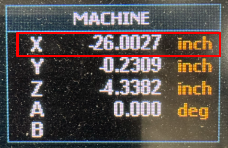
Save this value for later:
Slot 1 = X1
Slot 2 = X2
Slot 3 = X3
Slot 4 = X4
etc...
Now repeat this step for each and every fork you have installed. Leave the Z alone... jog forward in Y to clear the forks, then move X to the next fork position and repeat.
Lastly Capture Y
Now it's time to delicately capture the Y position. You should be immediately in front of your last tool slot with the fork barely touching the ISO20 tool holder with your final slot's X position captured.
Now's a great time to slowly jog the carriage backwards until you feel you've hit the rear of the fork. Move slowly and carefully and only in Step mode... not Continuous so you can remain in full control of the movement.
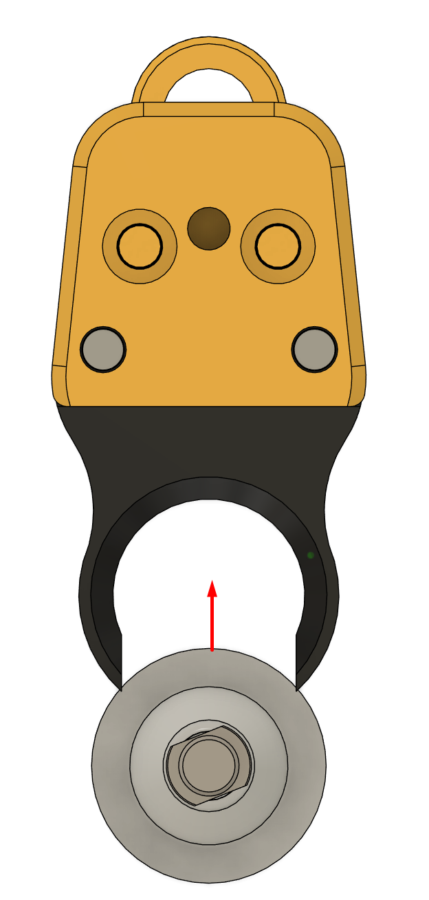
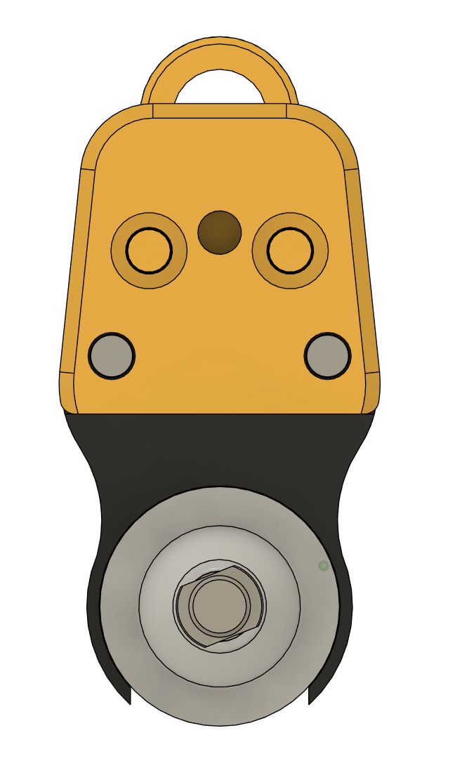
Since our Forks are aligned in the rear and only differ in the X coordinate... for all of your forks the Y and Z coordinates are identical.
Now you can capture the Y coordinate.
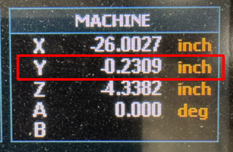
Slots = Y
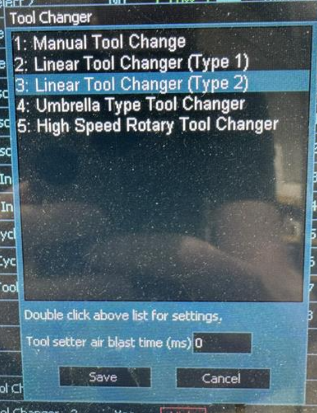
Step 2: Select Linear Tool Changer Type 2
On the MASSO controller:
- Go to F1 Setup.
- Open the Tool Changer section.
- Select Linear Tool Changer Type 2.
- Double-click the tool changer to open the configuration window.
Step 3: Understand the Fork Motion
For tool forks, MASSO needs to know three main things:
- Where each fork is located: this is the center position of each tool slot... the X and Y coordinates we captured in Step 1
- Where to approach from: this keeps the spindle/tool holder clear before sliding into the fork.
- What Z height to use: this is the height where the tool holder is seated in the fork and the spindle can clamp/unclamp the tool. Also captured in Step 1
In our example setup, the forks are arranged in a straight line across the X axis. The spindle approaches each fork from the Y direction, slides into the fork, releases or grabs the tool, then slides back out.
Step 4: Enter the Linear Tool Changer Settings
In the MASSO Linear Tool Changer configuration window, enter your tool changer settings.
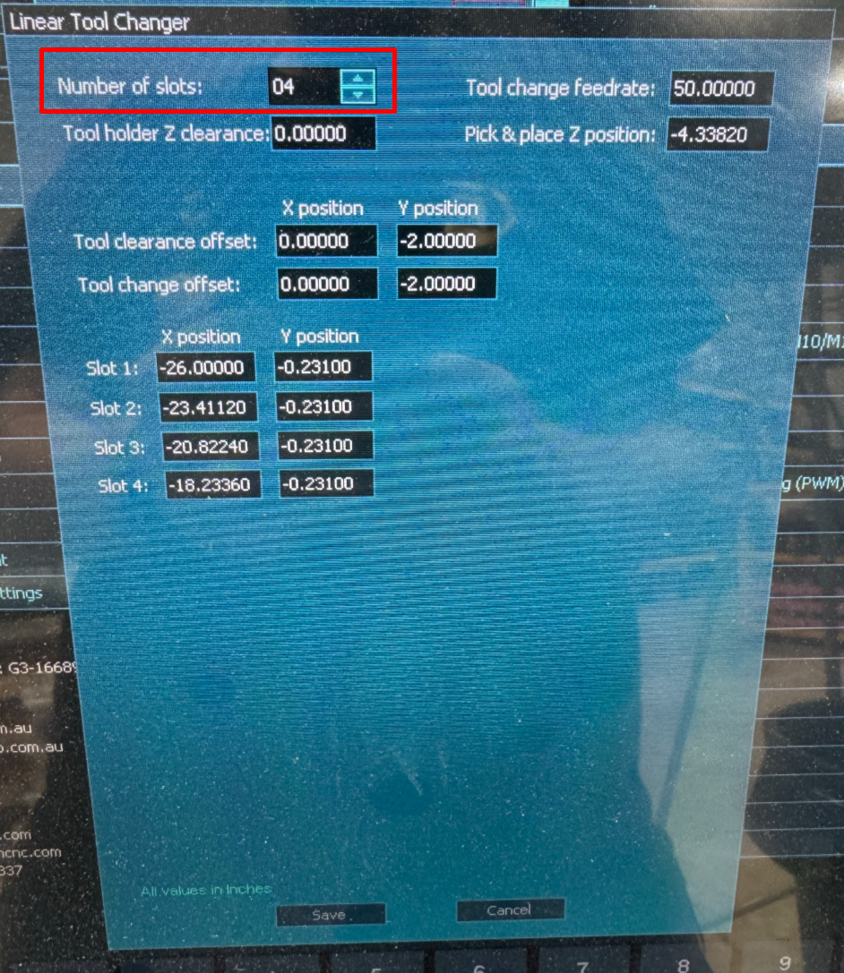
Number of Slots
Set this to the number of forks installed on your machine.
Example: 4
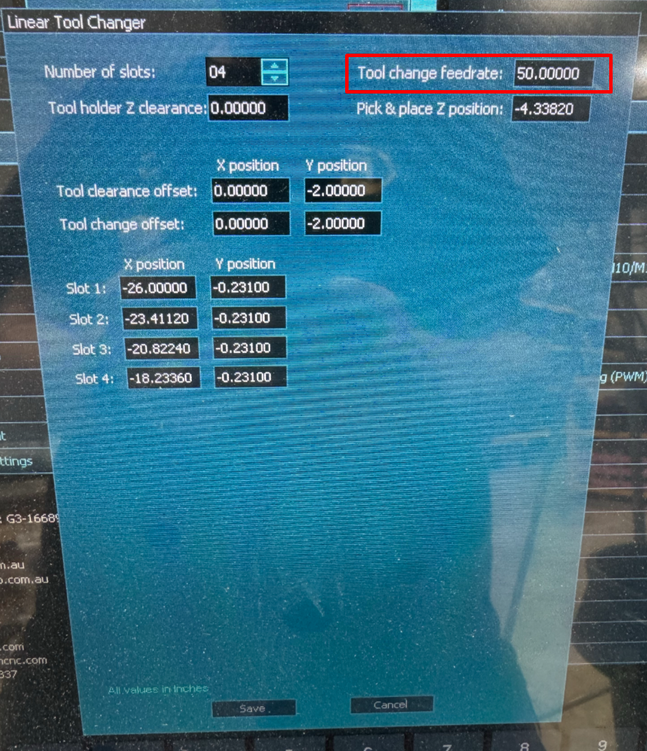
Tool Change Feedrate
This controls the feedrate used when sliding the tool holder into and out of the fork.
Start slow. You can increase it later after the tool change is proven reliable.
Example: 50 in/min
Pro Tip: Until you've got everything configured and tested, we recommend 10 in/min. This gives you plenty of time to react if things go wrong and you need to hit the e-stop.
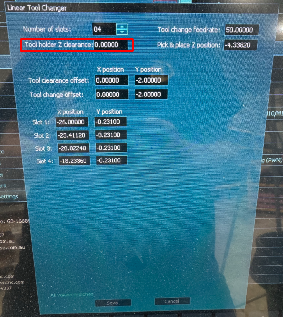
Tool Holder Z Clearance
This is the safe Z position MASSO uses after dropping off a tool and before moving to another slot.
Use a Z position that clears the tool holders, forks, and anything else mounted nearby.
By default, we recommend setting this to 0. After the tool is released, this is the Z height the z carriage moves up to ensure the bottom of the motor does not bump into the top of any of the ISO20 tool holders sitting in forks. Later you can tweak this for a faster tool change, but for now zero (0) is a very safe z position.
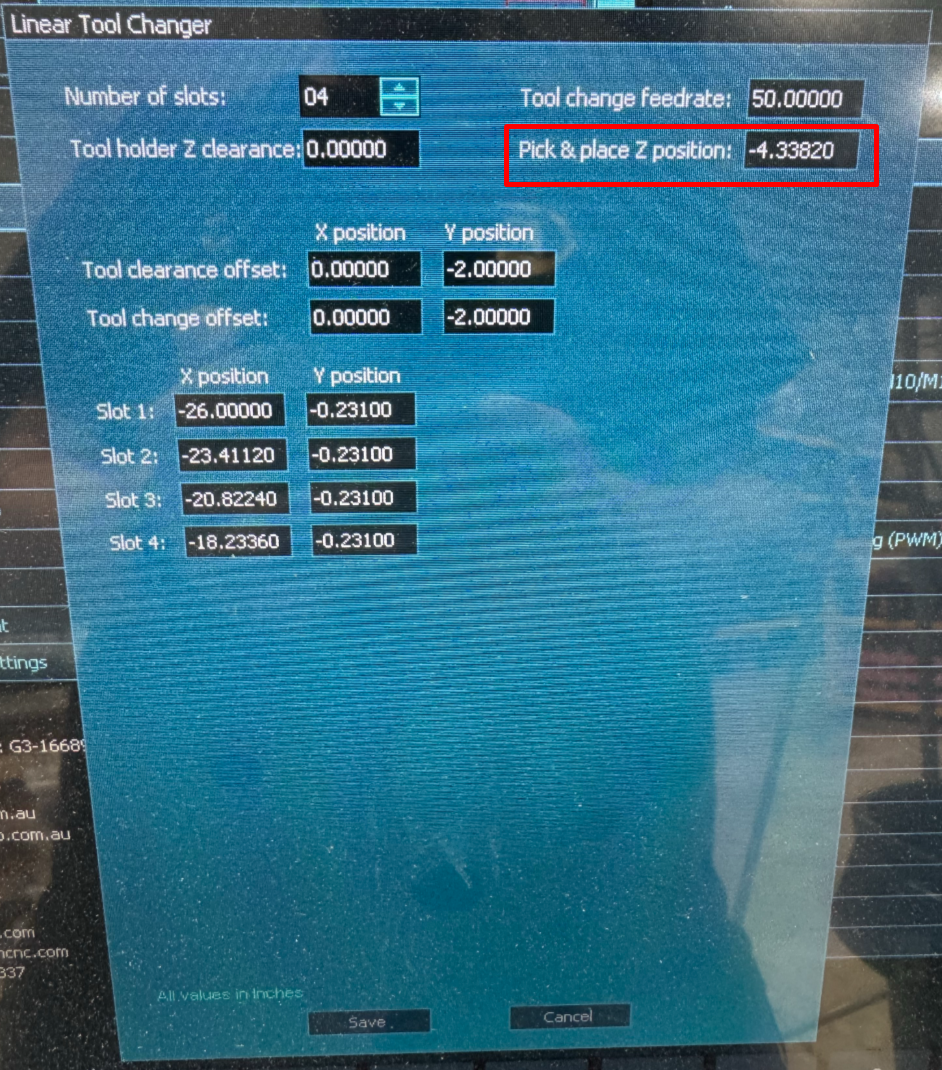
Pick & Place Z Position
This is the Z height where the spindle clamps or unclamps the ISO20 tool holder.
We captured this value in step 1: -4.3382
Note: Your value will be different.
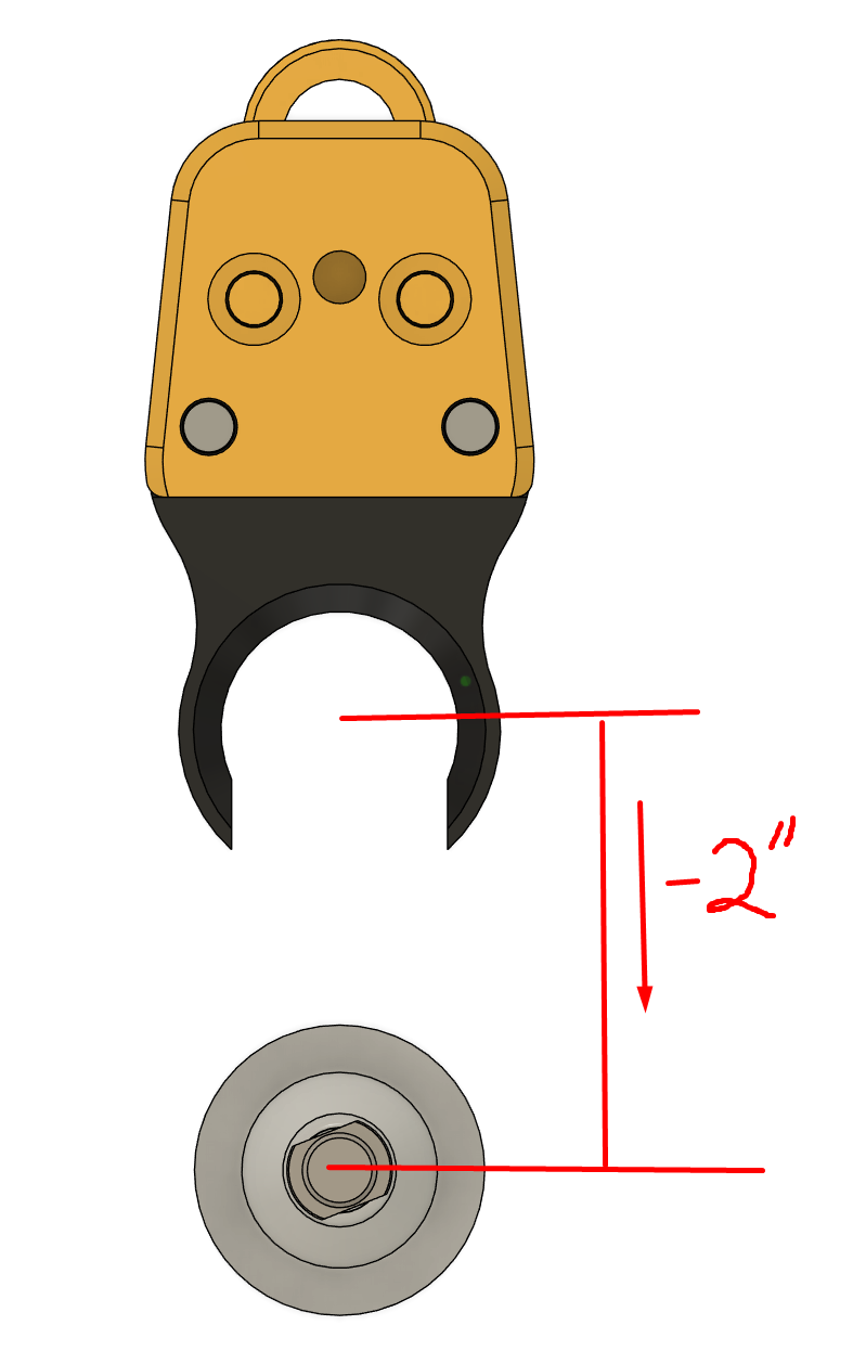
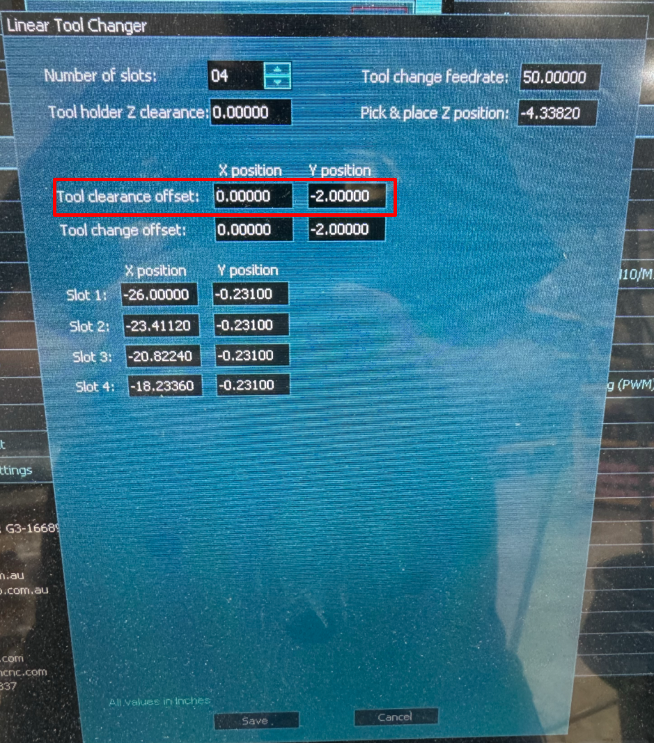
Tool Clearance Offset
This is the position MASSO moves to before beginning the tool change.
For a fork setup, this is usually the “in front of the fork” position before sliding into the holder.
Example:
- X Offset: 0.0000
- Y Offset: -2.0000
Note that the offset is -2" which means the z-carriage will move 2" in front of the fork before dropping down to the proper Z height.
This offset may need to be adjusted if you're using a dust boot but anything between 1.5" and 2" is good in our testing.
Be careful to remember that the more forward you come on your machine (if it homes in the back right) the more negative. Thus this value is -2 so it is "in front" of the forks.
This is the offset used when "dropping off" the tool it is currently holding... and at the beginning of the tool-changing operation.
Tool Change Offset
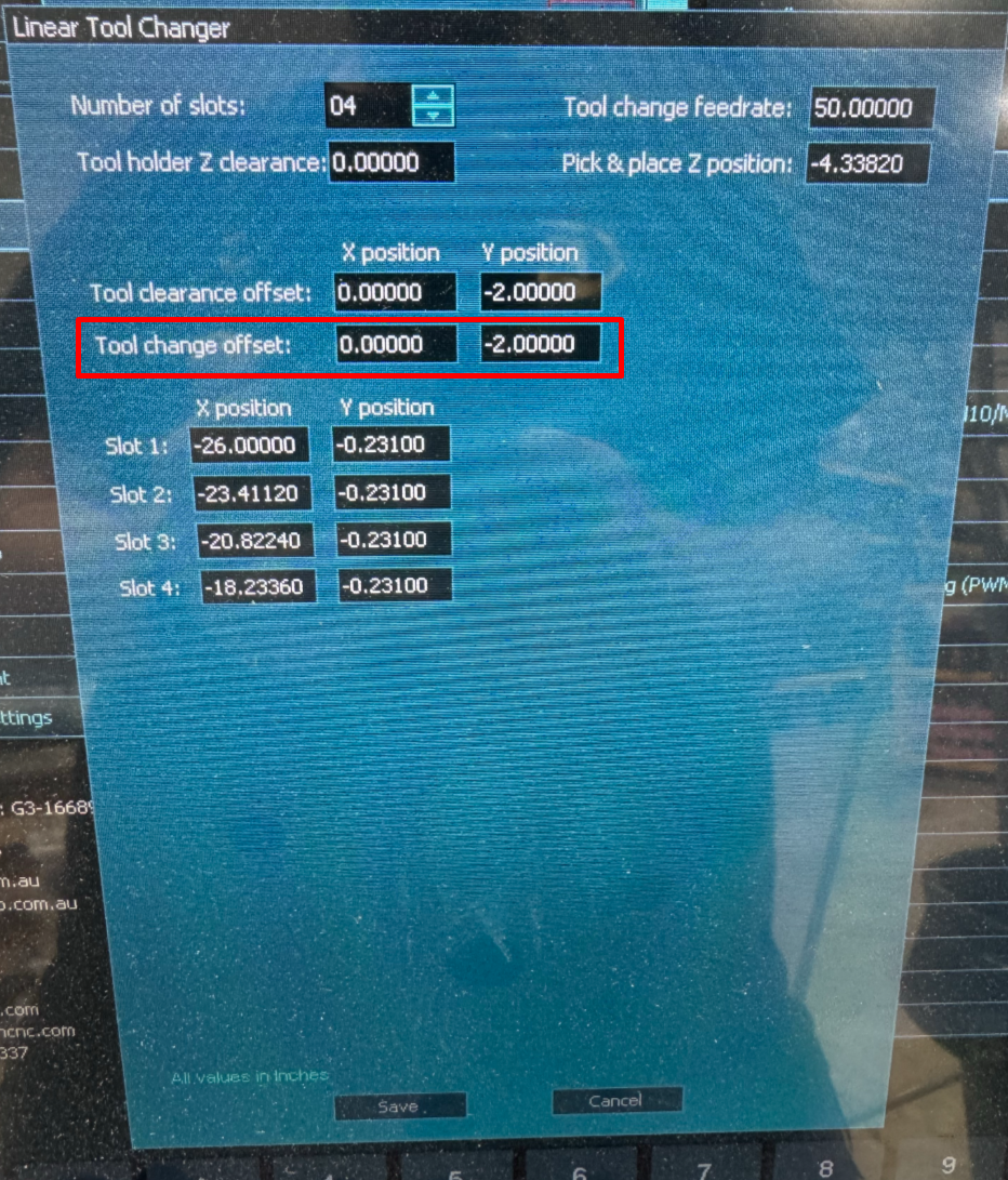
This is the position MASSO uses to slide into or out of the fork.
On our test setup, the tool clearance offset and tool change offset are the same. This tells MASSO to approach from the same direction and perform the fork entry/exit movement cleanly.
Example:
- X Offset: 0.0000
- Y Offset: -2.0000
This is the offset used after it "picks up" the new tool before moving up and back to carving.
Enter Y Position & X Positions of each Tool Fork
Now is when you'll enter the X position of each tool slot. Also enter the same Y coordinate in every slot position.
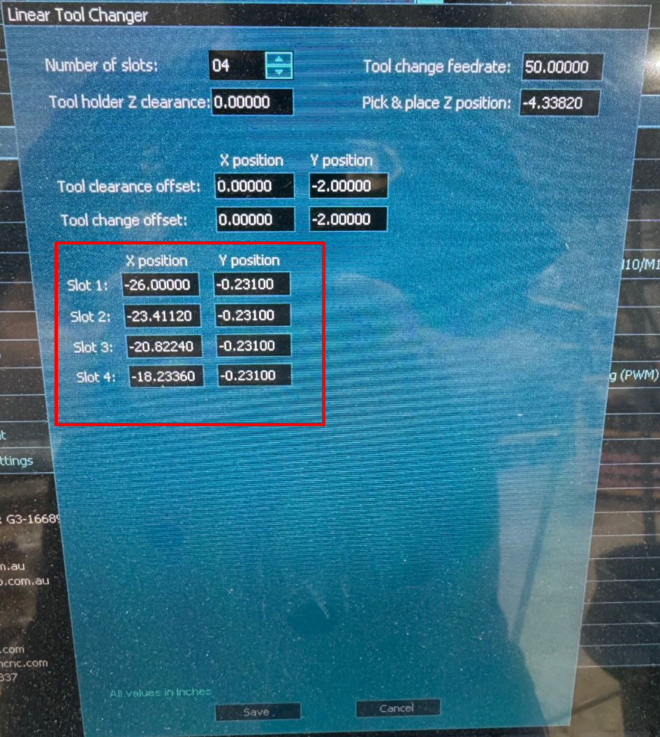
After all that hit Save and Save again. It's also a good idea to save your settings to your disk for safe keeping.
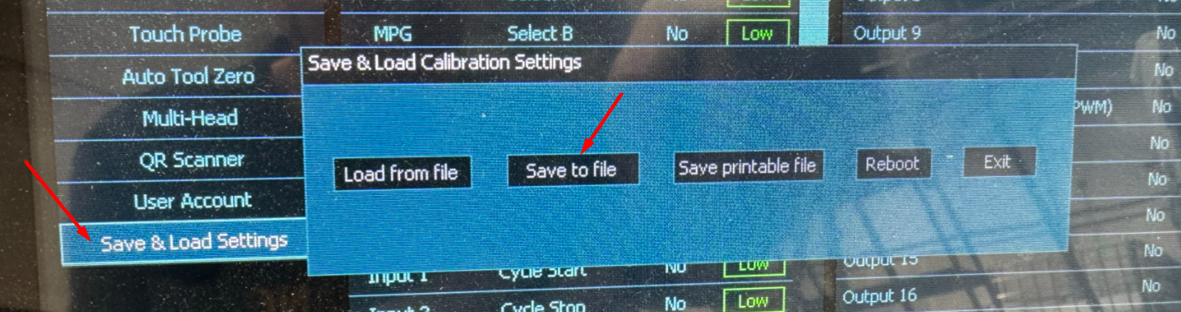
Step 5: Assign Tool Numbers to Slots
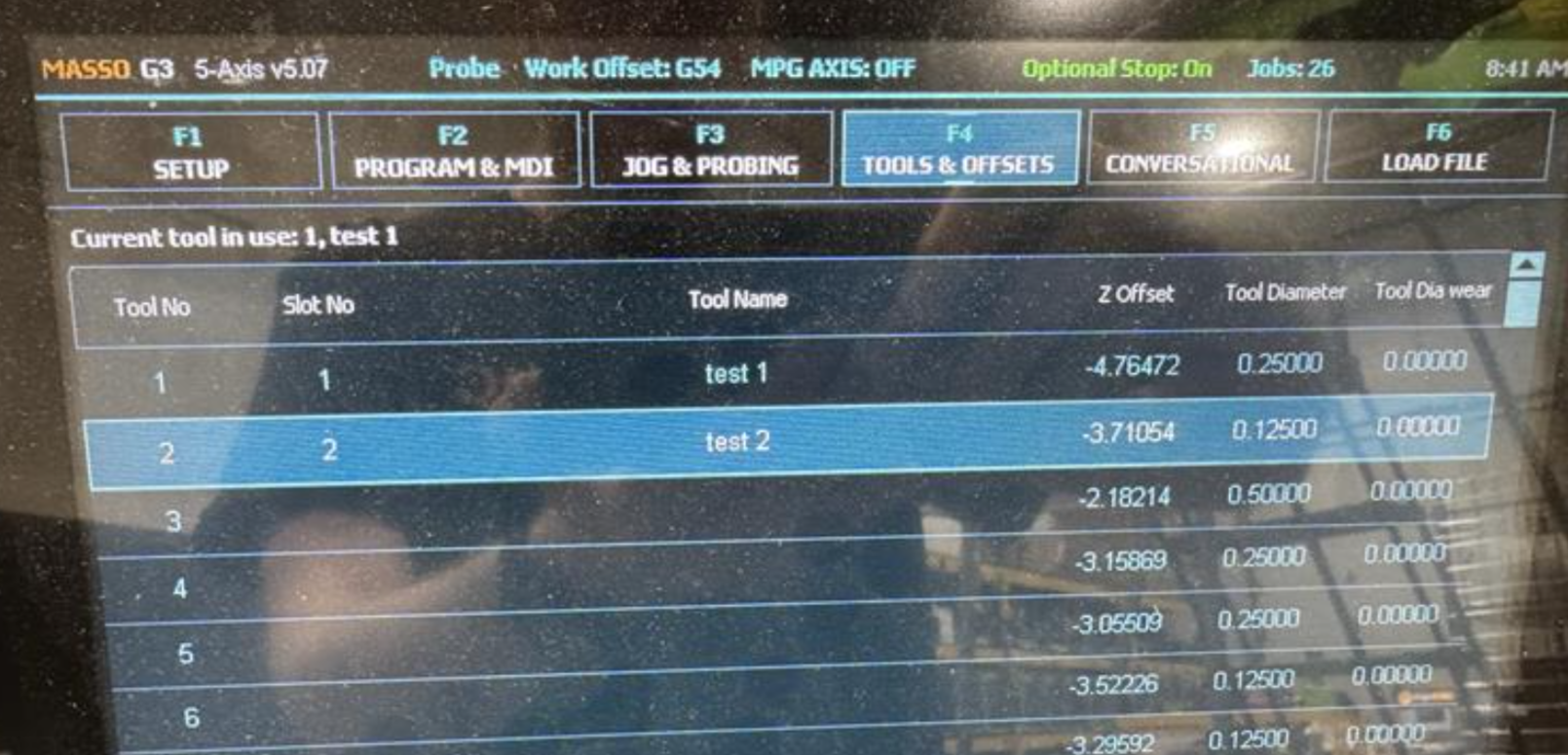
MASSO also needs to know which tool number lives in which slot.
Go to F4 Tools & Work Offsets and assign each tool number to the correct slot.
Example:
| Tool Number | Fork Slot |
|---|---|
| Tool 1 | Slot 1 |
| Tool 2 | Slot 2 |
| Tool 3 | Slot 3 |
| Tool 4 | Slot 4 |
If a tool is not assigned to a slot, MASSO can alarm during the tool change.
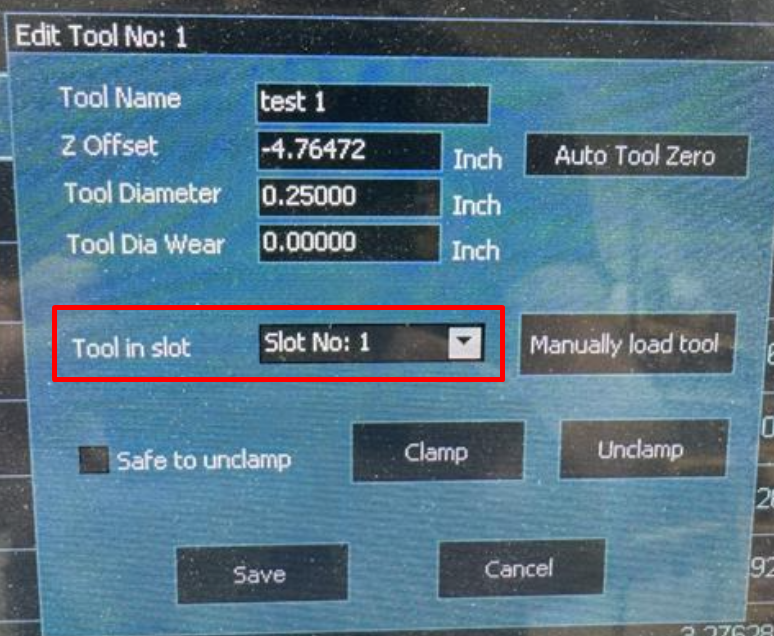
Step 6: Test Slowly
Before running a real program, test the tool changer carefully.
Recommended testing process:
- Remove unnecessary tools from the table.
- Keep your hand near the E-stop.
- Turn feed override down for the first test.
- Test one tool change at a time using MDI.
Example MDI commands:
T1 M06
T2 M06
T1 M06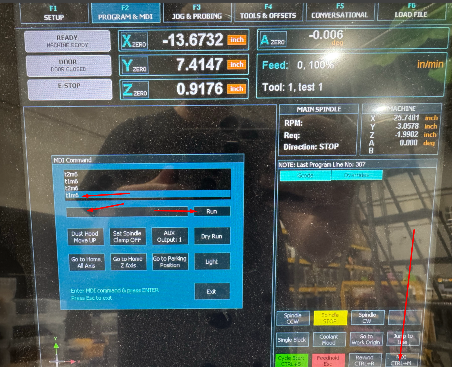
Watch the entire motion:
- The spindle should approach the fork without hitting the fork or holder.
- The holder should slide into the fork smoothly.
- The Z height should allow clean clamp/unclamp action.
- The spindle should slide away from the fork without dragging the tool holder.
- The tool-in-spindle sensor should correctly confirm whether a tool is loaded.
If anything looks wrong, stop and adjust the coordinates before continuing.
Troubleshooting
The spindle stops during the slide-in or slide-out move
Check the Tool Change Feedrate. MASSO notes that a feedrate of 0 can prevent the slide movement from happening.
The tool holder drags against the fork
The slot position, approach offset, or Z position may be slightly off. Recheck the machine coordinates and make small adjustments.
The spindle misses the fork
Recheck the slot X/Y coordinates. Make sure the machine was homed before the positions were recorded.
MASSO reports a tool error
Check that the requested tool is assigned to a slot in F4 Tools & Work Offsets. Also verify the drawbar and tool-detect sensor inputs are working correctly.
The tool releases but stays stuck in the spindle
Check air pressure, drawbar function, tool holder cleanliness, and the MASSO drawbar input/output status.
The spindle body or collet nut gets too close to the fork
Stop and adjust the fork location or Z position. The ISO20 holder should be supported by the fork, but the fork should not contact the spindle body or interfere with the tool holder release.
Final Notes
Take your time with the first setup. The goal is not to make the tool change fast right away. The goal is to make it repeatable.
Once the fork positions, Z height, tool changer feedrate, and tool assignments are correct, the fork-style ATC setup works very similarly to other MASSO-controlled ATC systems. The biggest difference is simply that the tool holder is sliding into a fork instead of dropping straight into a cup.
```

