


Wiring the Conversion Kit Core is relatively simple once you know a few tricks we've setup. We'll describe that here as you wire up ferrules inside of the Masso controller.
We've broken down the installation into several high-level steps which should be easy to follow. Each section is described more later in this article.
- Overall Controller View - lets you see the overall image that you're after when wiring up your controller.
- Wiring Steppers - this dives into both the controller side of the stepper cables and the motor side.
- Wiring Homing Switches - also diving into both controller and switch side.
- Powering your Conversion Kit - Overview of how the power works and where you can pull additional power if needed for various accessories.
- Bonus: Prewired Spindle Inlet Port
- Bonus: Wiring an MPG pendant
* Left click images to enlarge.
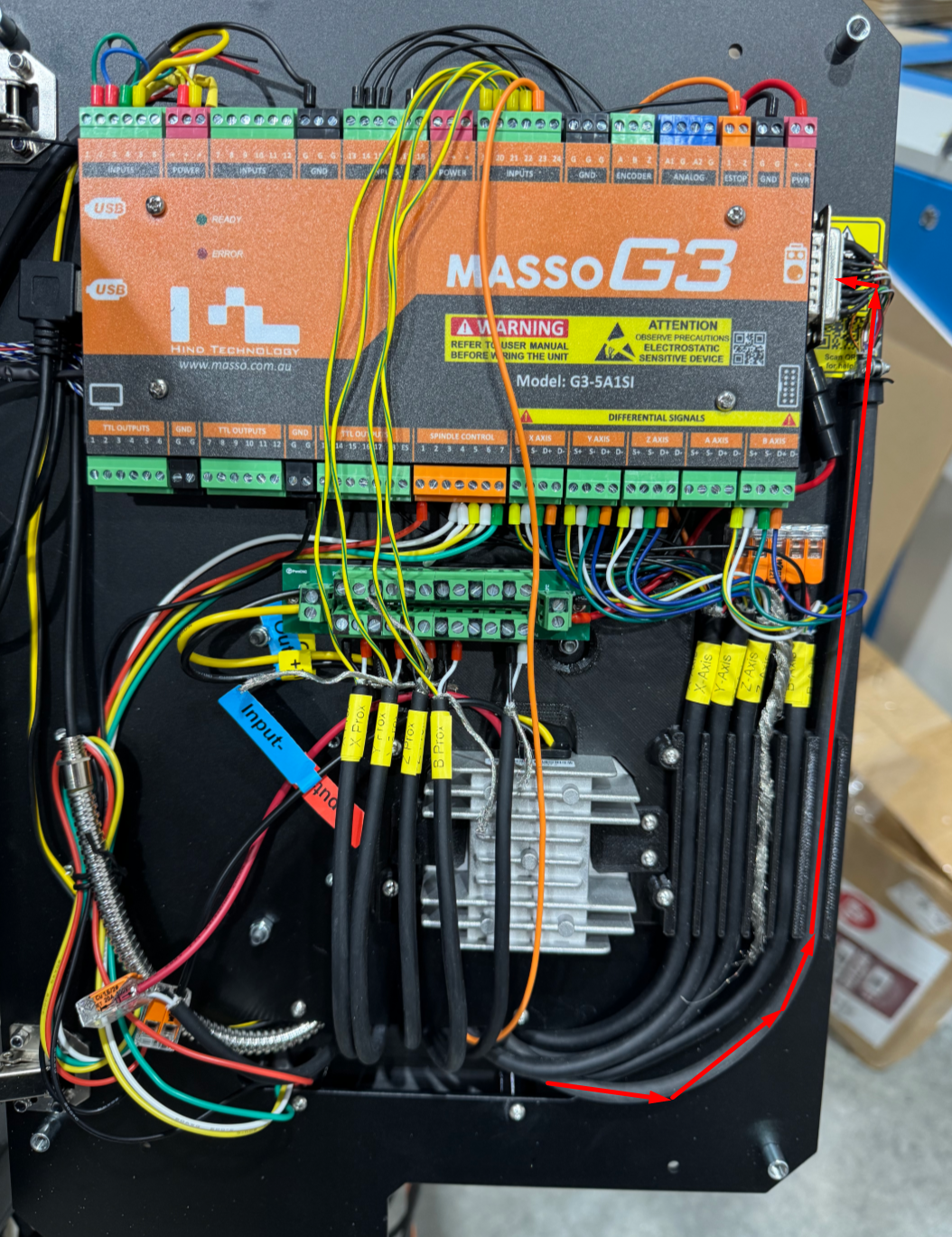
Overall Controller View
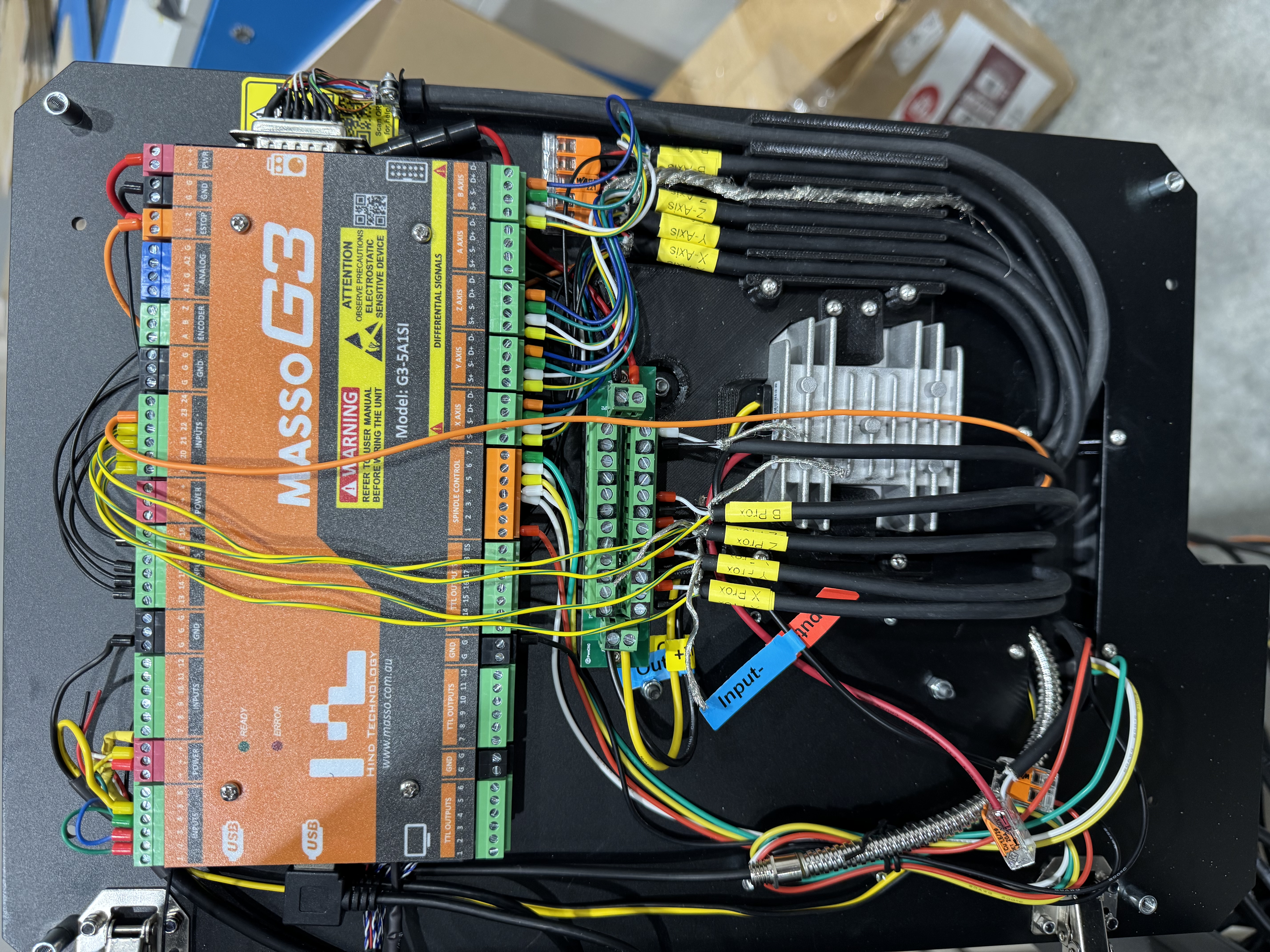
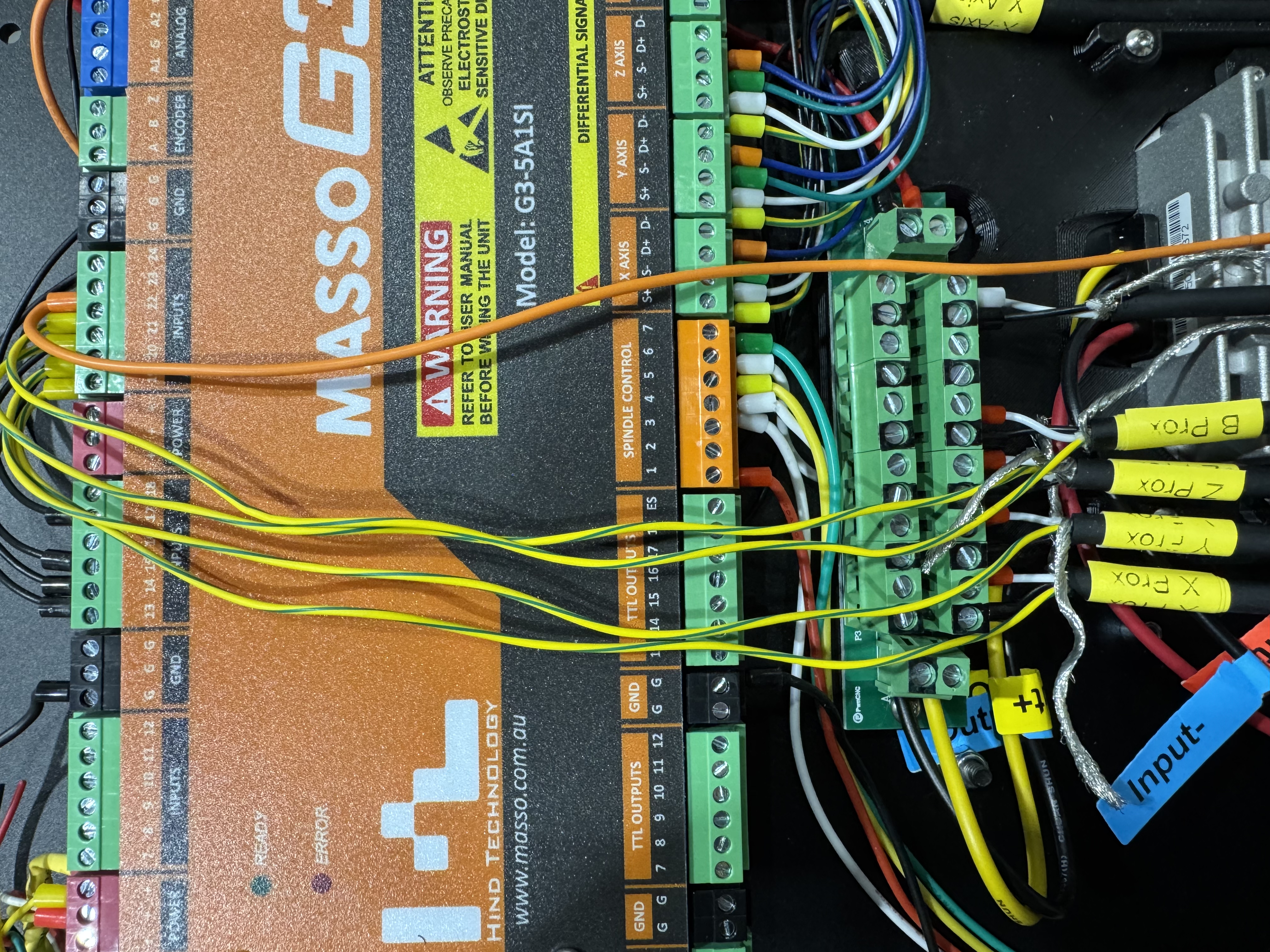
The following is an image of the wiring layout for our Core controller:
Wiring the Steppers
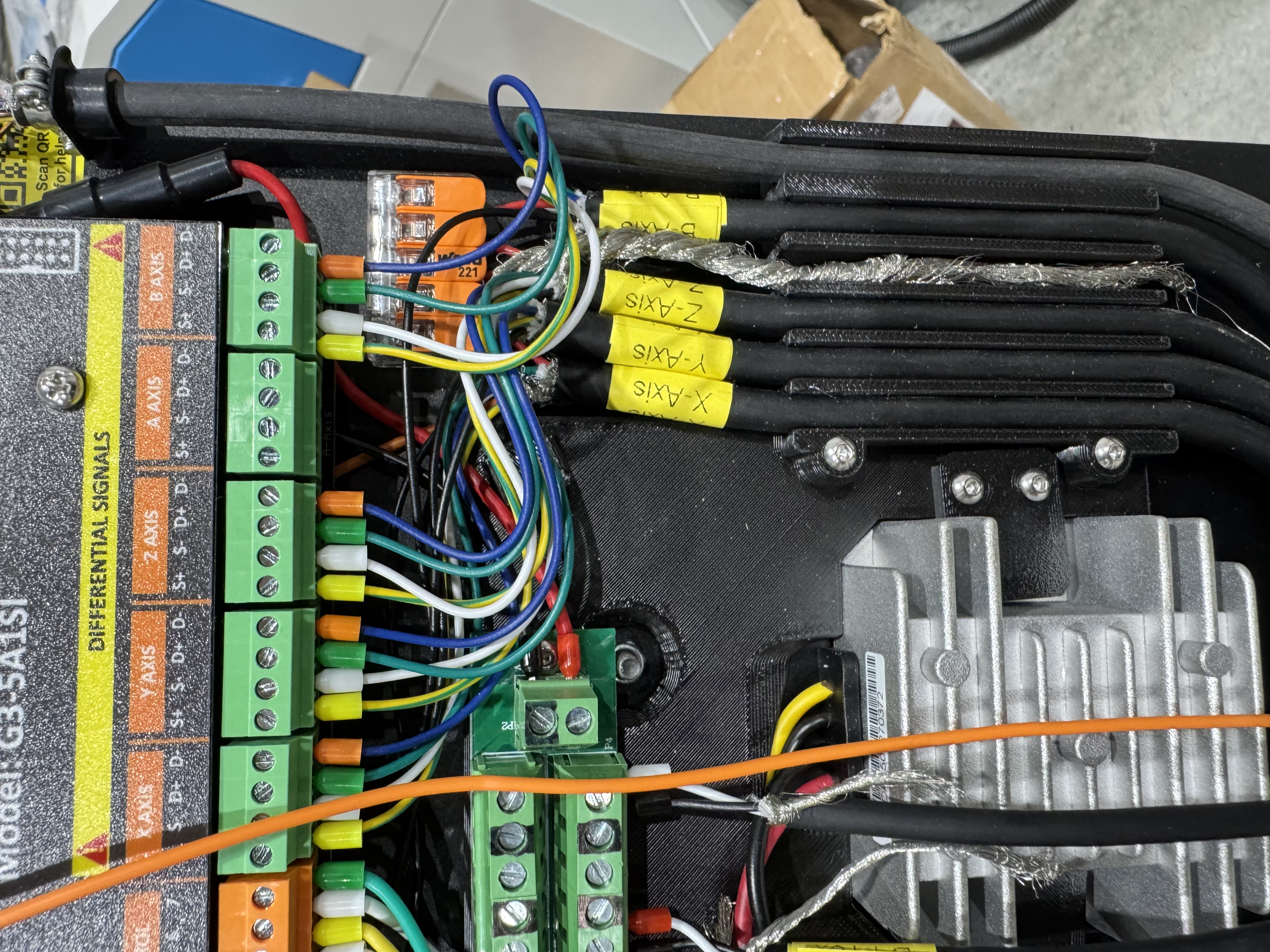
Wiring up your stepper motors is really easy and here's how. Run each stepper cable inside the controller's main enclosure along the right side. We've preinstalled a 3d printed framework for running your wires as easily as possible. The grooves along the right are for the stepper motor encoder wires. Secure each cable one at a time as you're wiring them into the controller as follows.
The Red wire gets wired first and goes directly into the WAGU connector above the grooves.
The Yellow, White, Green, and Orange wires get attached to the phoenix connectors for each axis.
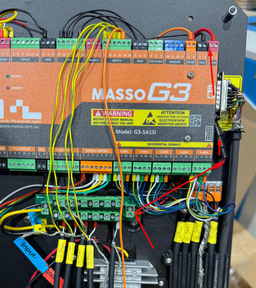
Lastly the Black wire gets brought to the top of the G3 controller and is wired into inputs as follows:
Input 13 = X Axis Alarm
Input 14 = Y Axis Alarm
Input 15 = Z Axis Alarm
Input 16 = B Axis Alarm
Wiring Stepper Motors
On the other side of the stepper cables are the motors. Wire them as shown in the following image.
To learn more about the DIP switches... please refer to this KB Article: https://support.pwncnc.com/kb/article/573-closed-loop-stepper-configuration/
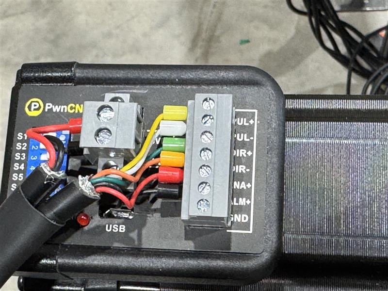
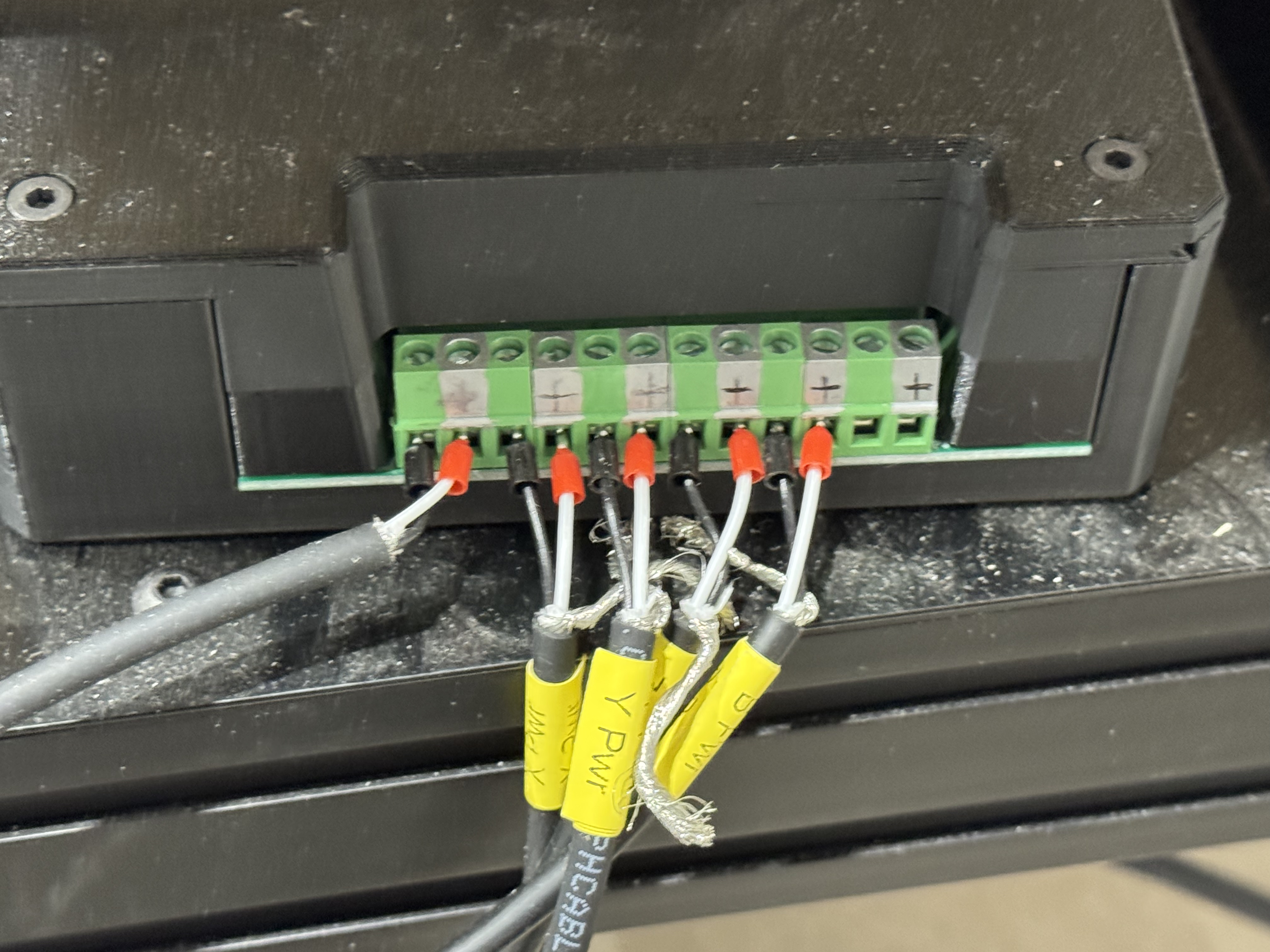
The 2-pin cable for each stepper can be wired directly into the main power supply unit.
Black = 0v
Red = 36v
* The image above has the terminals painted wrong. Your controller will have the 0v pins painted black while the 36v pins are not painted and the default green of the distribution board.
** If you have any doubts, please use a volt-meter to confirm the DC Power pins.
All the 0v/36v pairs are the same... and it doesn't matter which phoenix terminals you use so long as you're wiring black into black/0v and red into green/36v.
Wiring Homing Switches
The homing switches are unique in that they provide us with the input wire, but also require 24v power. This power is provided by the power-distribution board we've preinstalled.
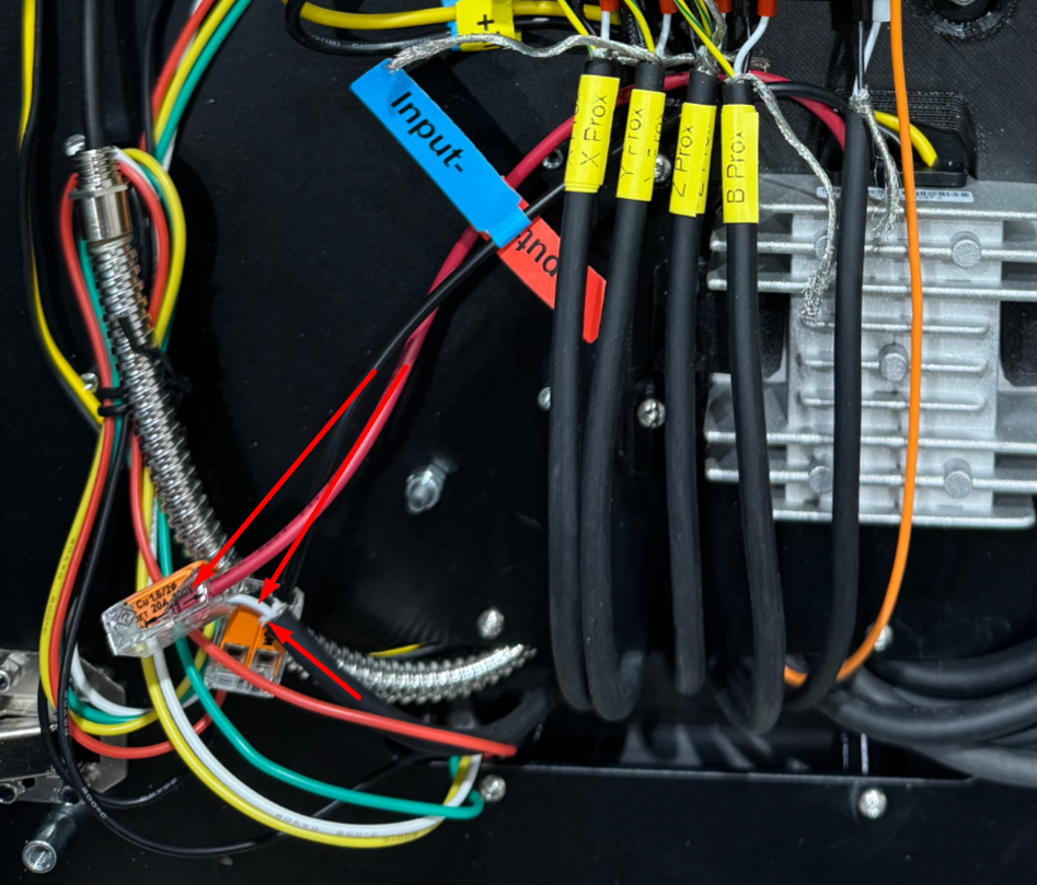
In the following image, notice how each homing cable is brought into the controller with the Red and Black ferrules wired into the power-distribution board.
The yellow wire is then brought to the top of the controller where it's wired into the following inputs:
Input 19 = X Proximity/Homing Switch
Input 20 = Y Proximity/Homing Switch
Input 21 = Z Proximity/Homing Switch
Input 22 = B Proximity/Homing Switch
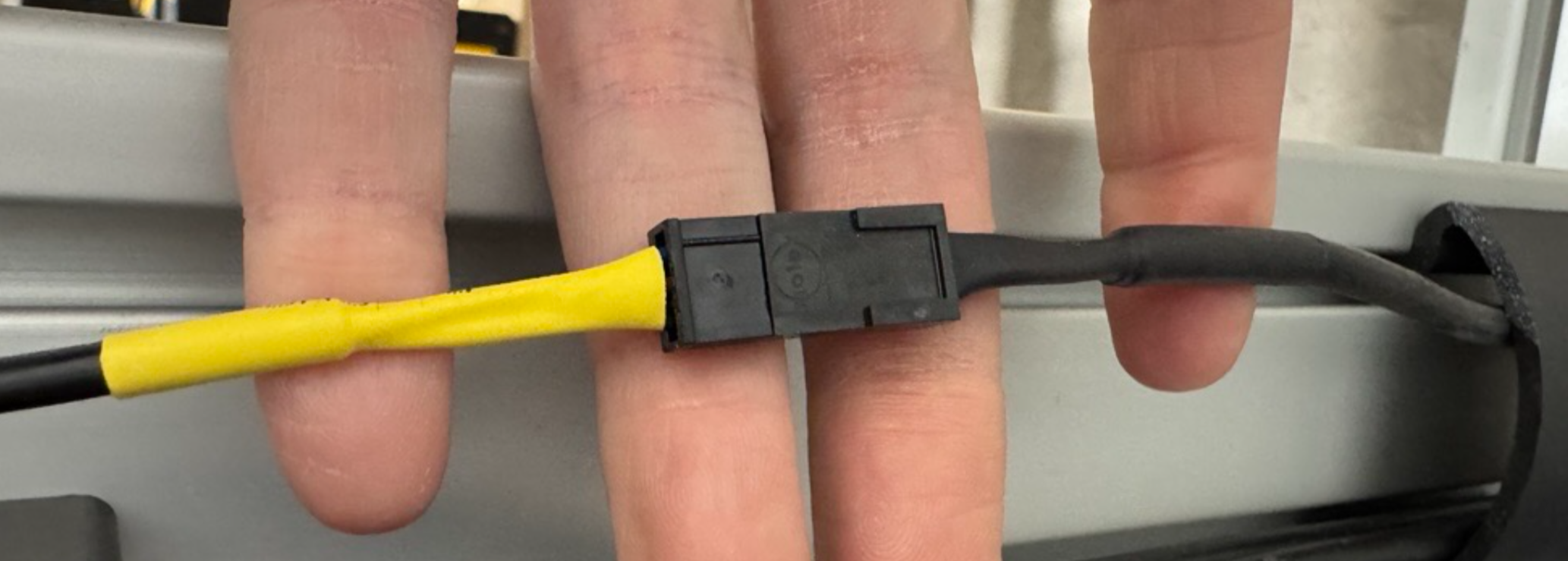
The switch side of these cables are extremely simple molex and there should only be one way to plug them together.
Powering your Conversion Kit
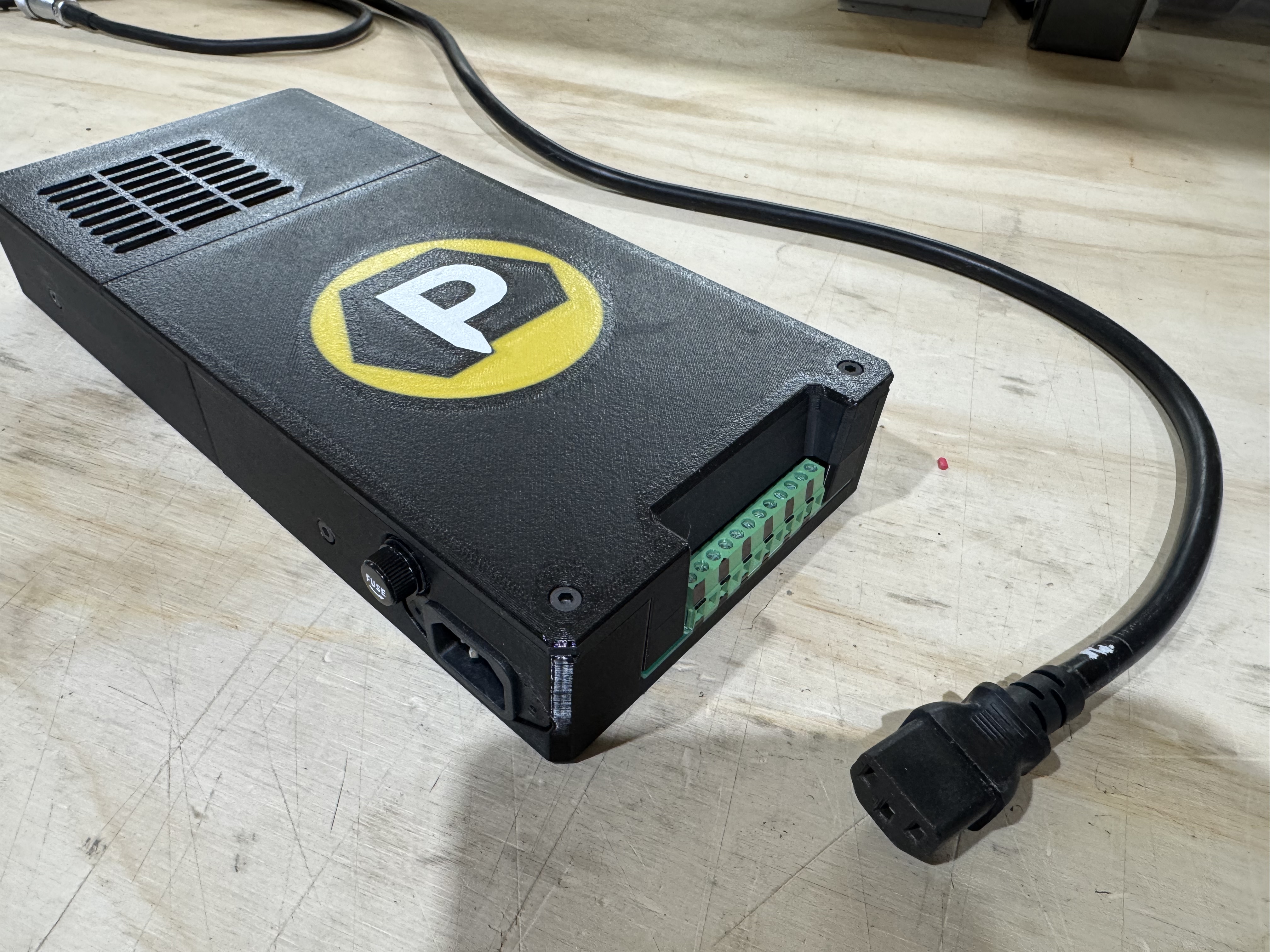
Your new conversion kit is powered by a Meanwell 36v power supply we've installed into a very simple enclosure. 36v DC power is available thanks to one of our power-distribution boards.
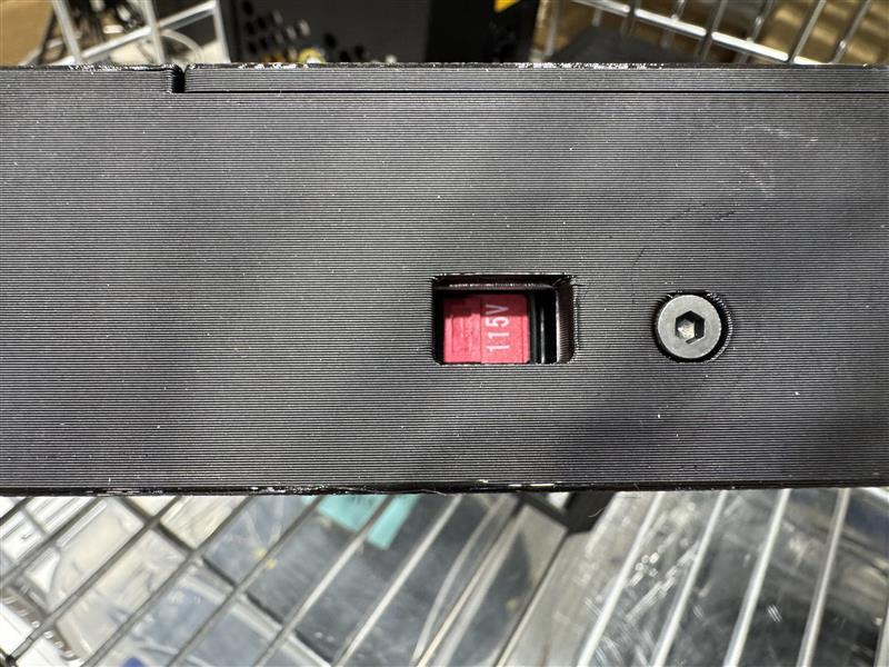
By default we have this switched to 110v input power. However if you're international or would like to power your conversion kit with 220v there is a switch on one side of the enclosure that must be flipped.
Additionally if powering with 220v, you'll have to provide your own power cable which needs a C13 connector on the power-supply side.
Powering your Controller
From the main power supply you will hookup the controllers power-supply cable:
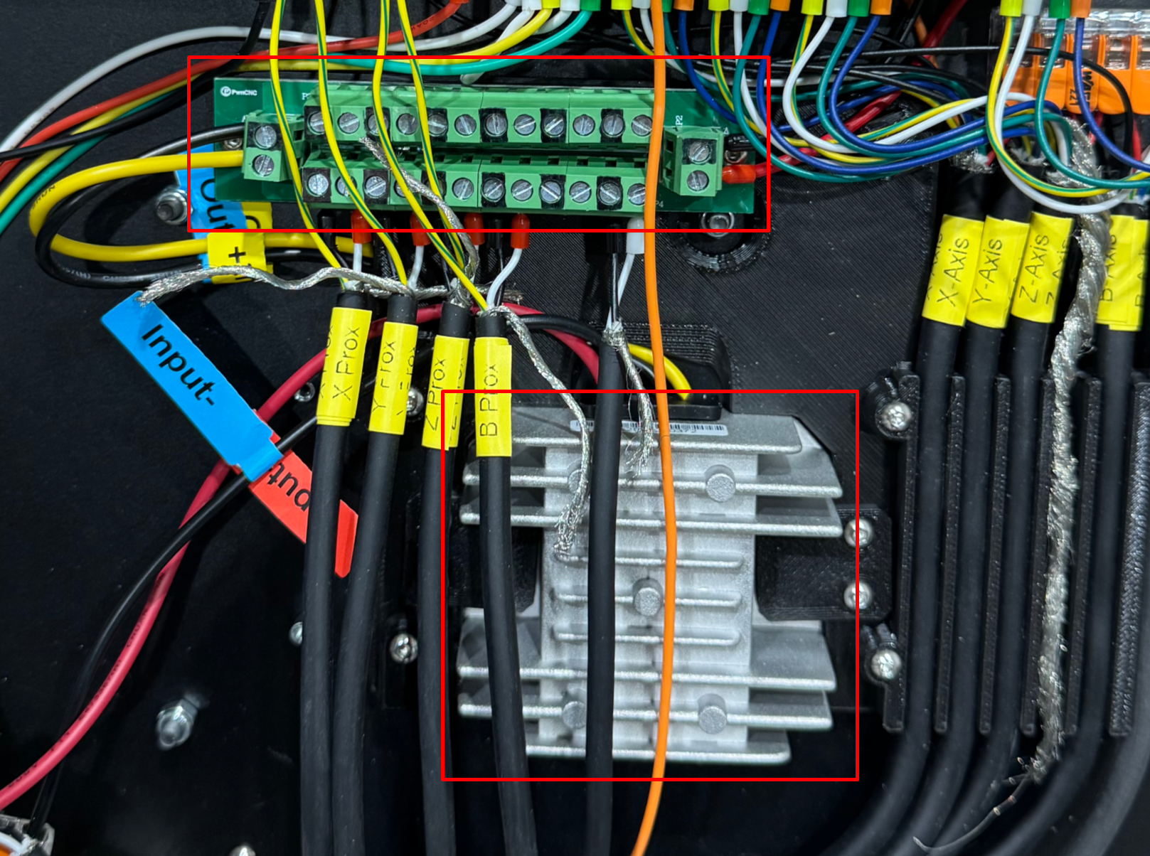
The cable on the far left leads to the controller. Inside of the controller this power cable is hooked into two WAGU connectors as shown below and ultimately lead into the large silver step-down converter.
The step-down converter converts 36v incoming power into 24v power used by the G3 controller and other accessories. The output is wired into a power distribution board to make it easier for you to hookup various accessories.
Note that we have pre-wired the controller through the necessary fuse and up to the top-right of the G3 Controller itself. The fuse is tucked along the right side of the main G3 controller unit.
The entire distribution board is charged with the 24v power and works the same as the main power unit. Terminals marked black are 0v while the green terminals are 24v.
In this image below you'll see 0v & 24v are powering the proximity switches. Just to the right of those prox cables is a cable we're using to power our LED strip under the gantry... an optional accessory.
Bonus: Prewired Spindle Inlet
In order to fully support a plug-n-play spindle system we're most known for... we've pre-installed the GX12 6-pin inlet cable and pre-wired it into the orange phoenix connector.
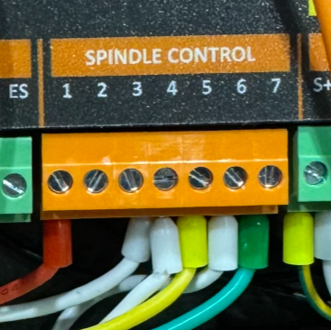
The pinout for this connector is as follows:
GX12 Pin 1 = GND
GX12 Pin 2 = Spindle Control 1 - 0-10v PWM
GX12 Pin 3 = Spindle Control 5 - CW / Forward
GX12 Pin 4 = Spindle Control 4 & 7 - Digital Common
GX12 Pin 5 = Spindle Control 7 - CCW / Reverse
GX12 Pin 6 = N/A
Purchasing one of our spindle kits/systems and you'll be matched with the proper control cable for this inlet.
Extra Bonus: Masso MPG
As an extra we have added an additional groove for securing your MPG cable that runs along the right inside of the controller.
Remember to swap whatever ferrules are wired into the e-stop pin 1 over to pin 2 if you're attaching the MPG. This way the MPG's e-stop will work along with the main e-stop on your Masso Touch controller.
If you have any questions or need further assistance please reach out to us at [email protected]

