


Manual Mode Operation
Spindle Systems have a convenient switch on the side of our enclosure which lets you switch between "Manual Mode" and "Automatic Mode". When flipped to manual (up or 1 position) you can hit the run button on the VFD's keypad and turn the dial controlling the motor just like you would a palm router.
See more: https://support.pwncnc.com/kb/article/658-phase-2-manual-mode-operation/
Spindle Kits come programmed for immediate use in "Manual Mode". This means you hit the run button and turn the dial to start your spindle motor just like you would a palm router.
See more: https://support.pwncnc.com/kb/article/655-phase-2-manual-mode-operation/
Wiring your Spindle to the SuperLongBoard(-ext) Controller for Automatic Mode Operation
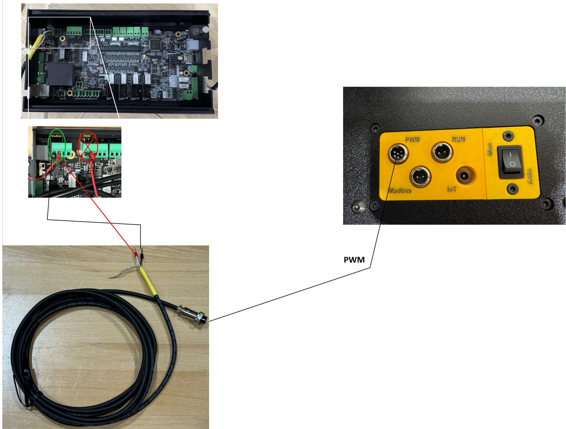
Spindle System Wiring
See more: https://support.pwncnc.com/kb/article/659-phase-3-controller-wiring-and-automatic-control/
If you have our spindle system, then it's really easy to plug everything up.
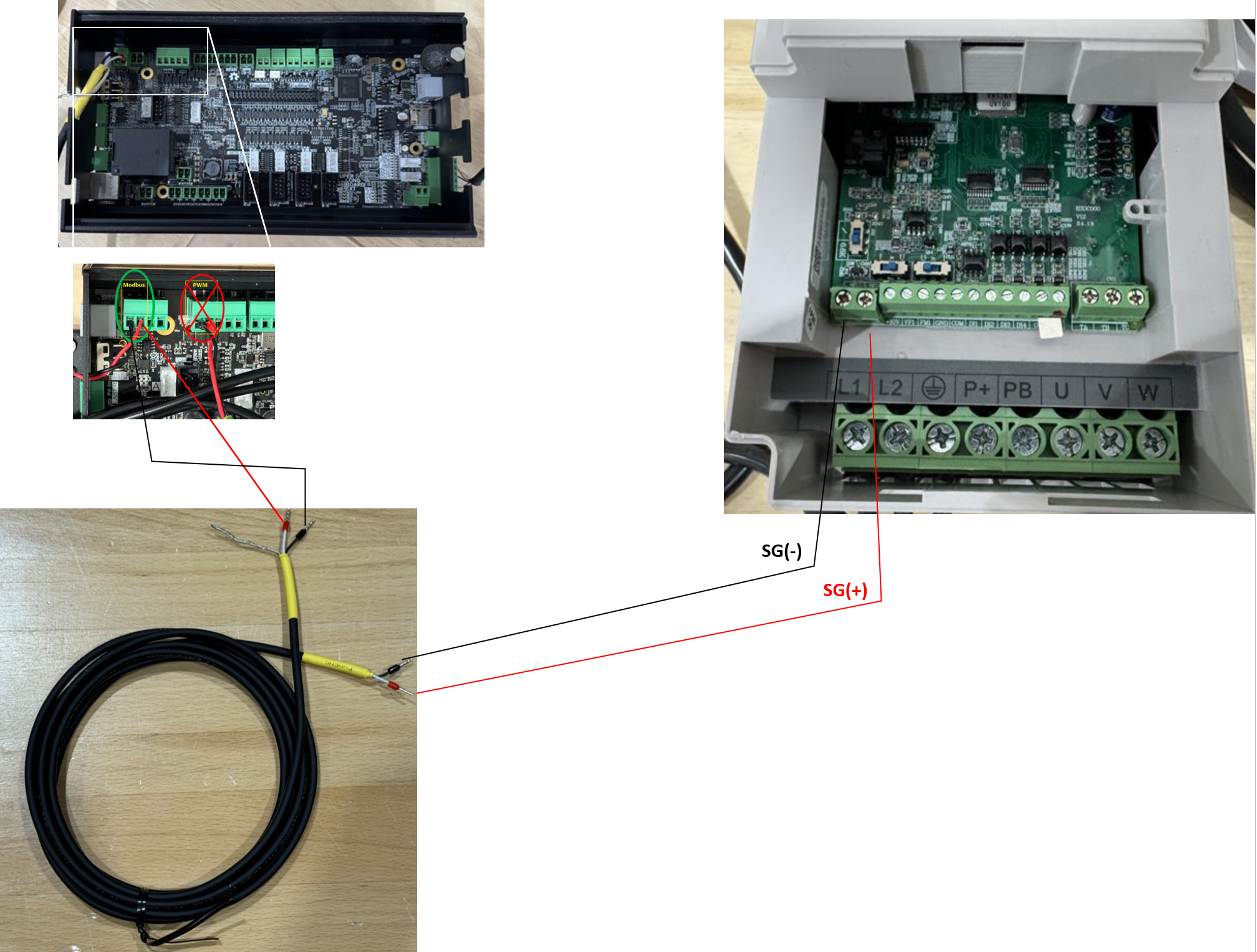
Spindle Kit Wiring
See more: https://support.pwncnc.com/kb/article/656-phase-3-controller-wiring-and-automatic-control/
If you have our spindle kit, then you'll be digging into the VFD directly to wire it up. Connect it as shown below:
Setting up your VFD for Automatic Mode Operation
This mode is where your CNC controller controls the VFD via Modbus/RS-485 communications connection signal. For SuperLongBoard(-ext), your controller is able to control CW/Forward, CCW/Reverse, and the 0-24000rpms.
Running Spindle Systems in Automatic Mode
See more: https://support.pwncnc.com/kb/article/659-phase-3-controller-wiring-and-automatic-control/
We have pre-programmed your VFD to run in automatic mode when the Manual Override switch is flipped to automatic (down or 0 position). The vfd will digitally communicate with your SuperLongBoard(-ext) Controller over Modbus, also known as RS-485, for telling the spindle how fast it should spin and in which direction. When your controller tells the spindle to stop moving... the VFD's will be in standby/stopped mode with a blinking keypad display. When your controller tells the spindle to run at a certain speed, your VFD will be changed to spin/forward mode with a solid keypad display showing the RPMs it was told to spin the motor at.
Running Spindle Kits in Automatic Mode
See more: https://support.pwncnc.com/kb/article/656-phase-3-controller-wiring-and-automatic-control/
Our spindle kits do not come with a vfd enclosure and as such you're expected to provide that as well as properly wiring up the high-voltage electrical. If unsure, consult an electrician.
Without our specially designed enclosure, our spindle kits can only run in Manual-Mode OR Automatic-Mode, you are unable to easily switch between them without changing a few program settings within the VFD.
To reprogram your VFD from Manual-Mode operation to Automatic-Mode operation you'll need to change the following settings:
Learn how to navigate your VFD programming here: https://support.pwncnc.com/kb/article/664-how-to-program-your-vfd/
P0.0.03 = 2
P0.0.04 = 9
P0.0.11 = 6
P2.0.02 = 21
P4.1.00 = 4
P4.1.01 = 3
Your VFD will now perform two-way communications with the SuperLongBoard(-ext) controller. The controller now uses the Modbus/RS-485 wires to know how fast it should spin the motor as well as when to switch from Stopped/Standby to CW/Forward to CCW-Reverse.
When your VFD is told to switch from Run Mode the vfd will change from standby/stopped mode (blinking keypad display) to spin/forward mode (solid keypad display).
In Run Mode, the VFD will also spin the the commanded RPMs which will be displayed on the VFD's keypad.
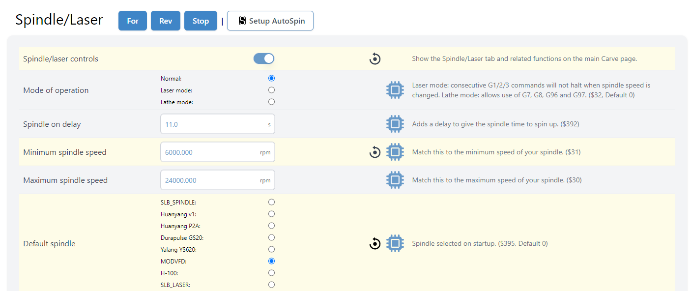
Setting up your SuperLongBoard(-ext) Controller for Automatic Mode Operation
We're experts in our VFD and spindles, but not experts in your particular CNC Controller. If you have specific questions, we will encourage you to seek advice and guidance from your machine provider.
We have played with SuperLongBoard(-ext) controllers before and here are a few notes we've gathered as to how to configure it for controlling a spindle:
CONFIGURING gSender (grblHAL Modbus)
Modbus requires correct firmware configuration.
We strongly recommend exporting your current settings before making changes:
gSender → Config → Export
This will produce a .json file with your settings inside.
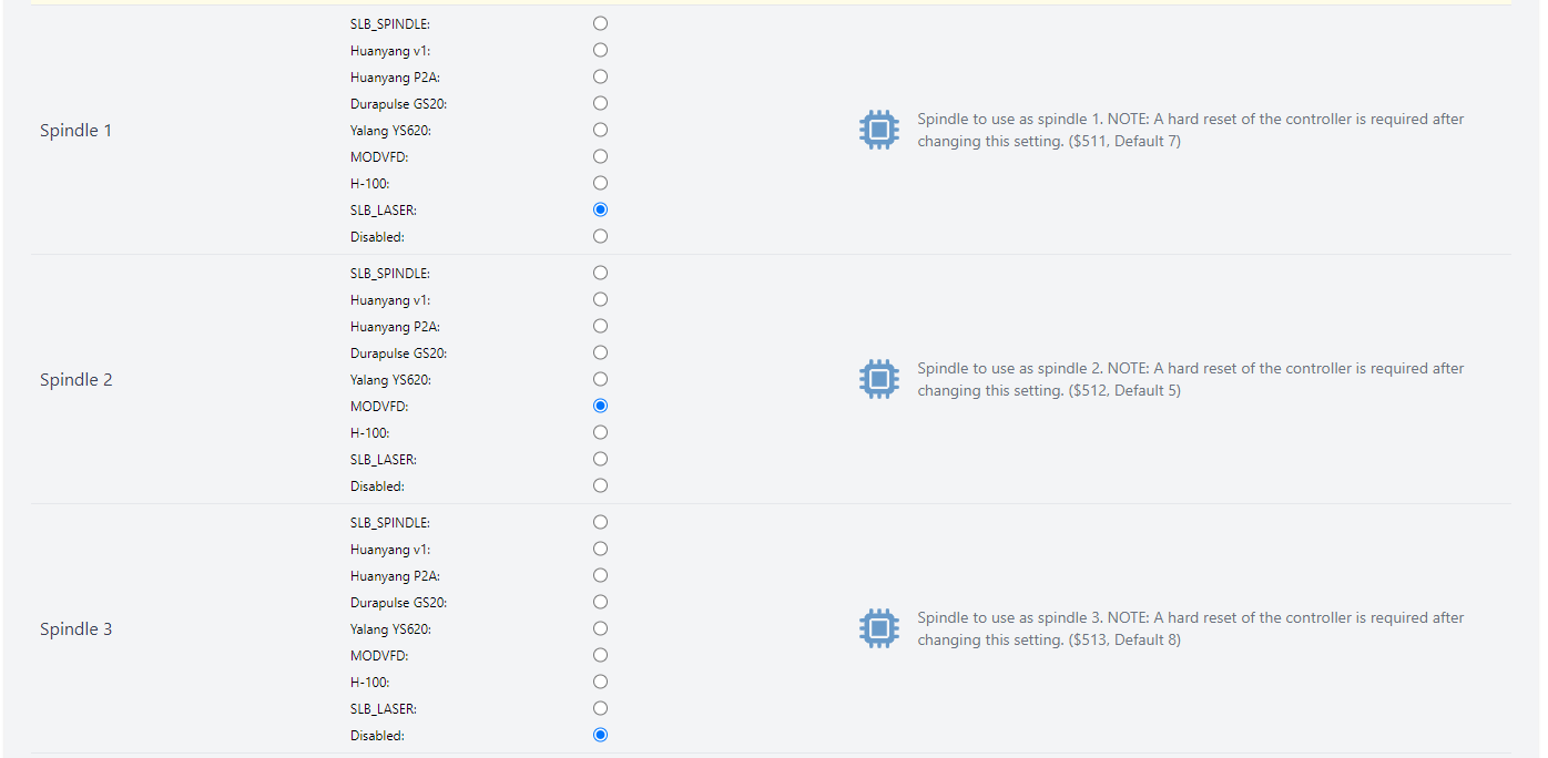
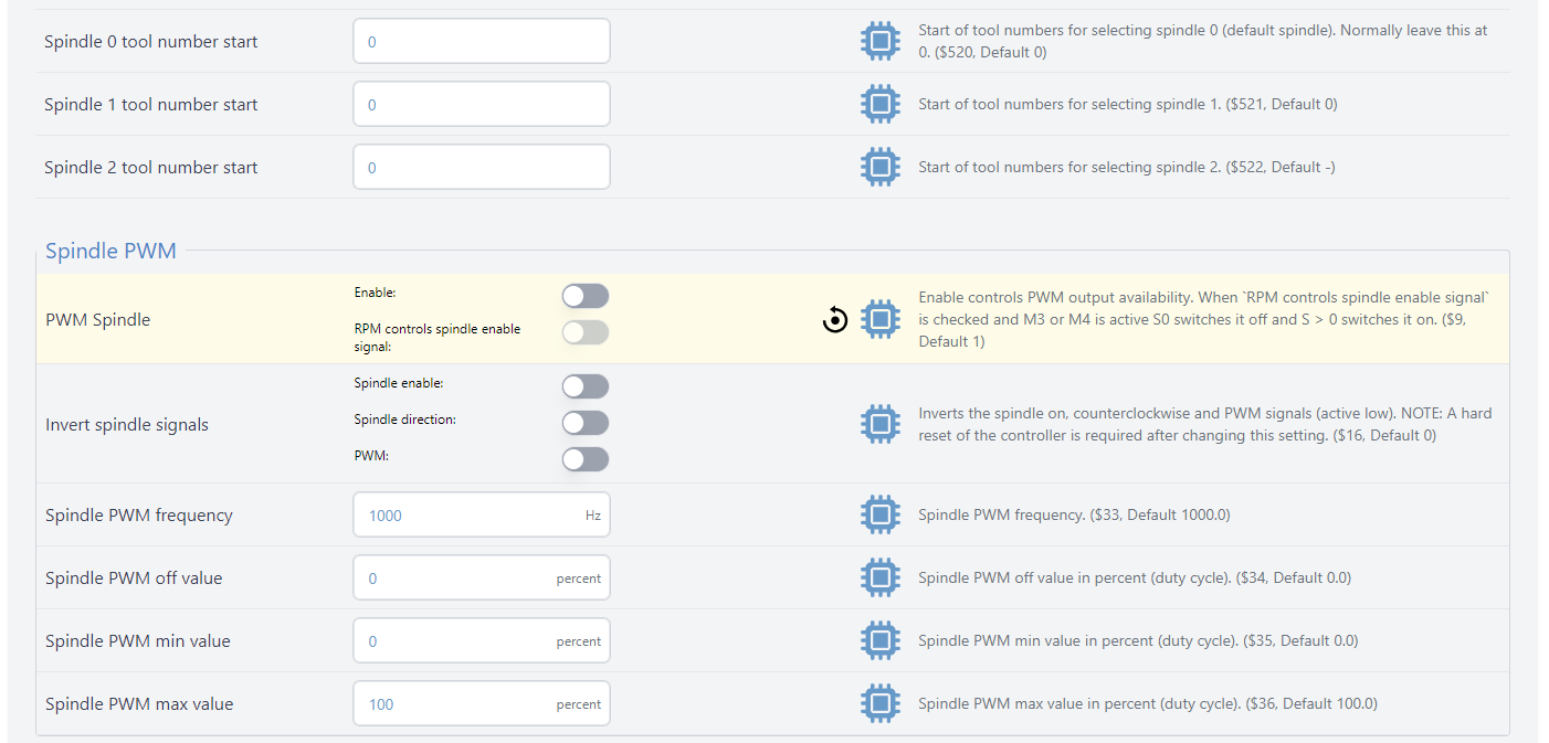
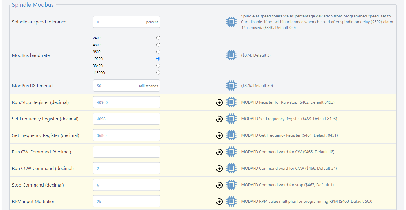
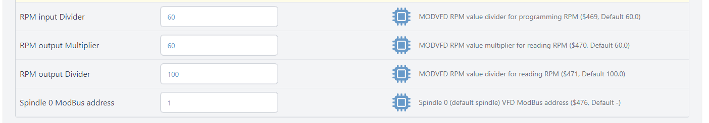
Known Working grblHAL Settings
The following values must match exactly:
$16 = 0
$30 = 24000
$31 = 6000
$340 = 0
$374 = 19200
$375 = 50
$392 = 6
$395 = MODVFD
$462 = 40960
$463 = 40961
$464 = 36864
$465 = 1
$466 = 2
$467 = 6
$468 = 25
$476 = 1
If $476 is unavailable, check neighboring parameter $478 for spindle address.
Baud rate must match between VFD and grblHAL.
If any value differs, correct it and reboot the controller.
ALARM 14 – WHAT IT MEANS
Alarm 14 in grblHAL is: “Spindle at Speed Timeout”
This means:
The controller did not receive confirmation from the VFD that the spindle reached commanded speed within the allowed time.
Alarm 14 does NOT automatically mean:
• The spindle is defective
• The VFD is defective
• The motor is wired incorrectly
If manual mode works, this alarm is a Modbus communication configuration issue.
Common causes:
• Baud rate mismatch
• Slave ID mismatch
• Incorrect register mapping
• Spindle-at-speed confirmation not enabled
• Timeout shorter than acceleration time
FAST ISOLATION TEST
To verify Modbus communication:
-
Open gSender Console
-
Type: M3 S12000
-
Press Enter
Observe:
• Does spindle start?
• Does Alarm 14 trigger immediately?
• Does it start but stop after timeout?
If it starts and runs:
Hardware and Modbus are functioning. Check your post processor.
If Alarm 14 appears:
Configuration mismatch exists in grblHAL settings.
IMPORTING KNOWN WORKING SETTINGS
If configuration drift is suspected:
-
Export your current firmware settings
-
Import the PwnCNC provided settings JSON (attached to the bottom of this article)
-
Reboot controller
This resolves most cases immediately.
gSender VERSION NOTE
Some versions of gSender have demonstrated inconsistent Modbus behavior.
If experiencing persistent Alarm 14 issues:
• Install gSender version 1.5.4 or 1.4.2
• Configure spindle
• Once functioning, upgrading often retains working configuration
gSender releases can be found here: https://github.com/Sienci-Labs/gsender/releases
WHEN TO CONTACT SUPPORT
If you still experience issues, email support with:
• Screenshot of gSender Spindle Settings page
• Screenshot of full $$ output
• Photo of Modbus wiring
• Confirmation that spindle runs in manual mode
Incomplete requests may delay troubleshooting.
SUMMARY
If spindle runs in manual mode, hardware is confirmed working.
Alarm 14 indicates a communication timeout between grblHAL and the VFD.
The solution is configuration alignment, not VFD/motor replacement.


