


Article type: Machine-Specific Research
Machine family: Onefinity with Redline controller
Sensor manufacturer: F&C Sensing Technology
Sensor model: FC-SPX306
Output type: NPN
Operating voltage: 5–24 VDC
Research notice: This article documents hardware inspected and tested by PwnCNC while researching Onefinity-specific controller conversions. Manufacturers may change sensors, connectors, wiring, or other components without notice. Always confirm that your hardware matches the examples shown before making wiring changes.
Overview
Onefinity machines equipped with the Redline controller use an optical limit switch that operates from the controller’s 5 VDC sensor supply.
During our conversion-kit research, PwnCNC identified the sensor as an F&C FC-SPX306 NPN optical sensor. The sensor supports an operating range of 5–24 VDC, allowing it to be powered by the 24 VDC sensor supply used in our MASSO conversion-kit wiring.
This means the original optical sensors may be reused during a MASSO conversion rather than replaced, provided the sensors and wiring match the hardware documented in this article.
Identified Sensor
The model number printed on the sensor is FC-SPX306.
| Specification | Identification |
|---|---|
| Manufacturer | F&C Sensing Technology |
| Model | FC-SPX306 |
| Sensor type | Slot-style optical/photoelectric sensor |
| Detection method | Opposed-beam optical detection |
| Output type | NPN |
| Operating voltage | 5–24 VDC |
| Factory Redline supply | 5 VDC |
| PwnCNC conversion-kit supply | 24 VDC |
The manufacturer’s published specifications for the F&C FC-SPX306 confirm its 5–24 VDC operating range.
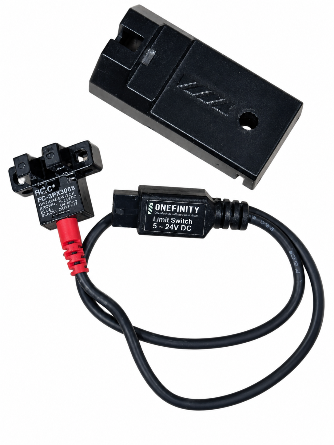
F&C FC-SPX306 optical limit switch, Onefinity cable and factory mounting hardware.
Verified Wire Functions
Opening the sensor allowed us to trace the conductors and verify how the Redline harness uses them.
| Wire color | Function | Redline configuration | PwnCNC MASSO conversion |
|---|---|---|---|
| Brown | Positive sensor supply | +5 VDC | +24 VDC |
| Blue | DC common / 0 V | 0 VDC | 0 VDC |
| White | NPN signal output | Redline sensor input | MASSO input with power/resistor jumper |
| Black | Unused in this application | Not connected | Not connected |
The blue wire is the sensor’s DC common or 0 V reference. It should not be confused with protective earth or the machine’s chassis-ground connection.
The black conductor is present in the cable but is not used by the Redline wiring configuration we inspected. It should remain disconnected and individually insulated unless its purpose has been independently verified for your exact sensor revision.
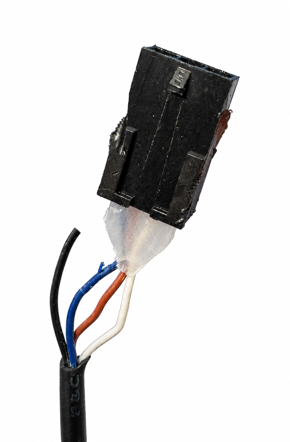
Internal wiring of the FC-SPX306 sensor. Brown supplies positive DC power, blue is 0 V and white is the NPN signal output. The black conductor is unused in this application.
Redline and MASSO Voltage Difference
The original Redline controller provides approximately 5 VDC to the sensor through the brown and blue conductors:
-
Brown: +5 VDC
-
Blue: 0 VDC
-
White: NPN signal
PwnCNC conversion kits use a 24 VDC industrial sensor circuit:
-
Brown: +24 VDC
-
Blue: 0 VDC
-
White: NPN signal to MASSO
-
Black: Disconnected
The voltage difference does not require replacing this sensor because the FC-SPX306 is rated to operate from 5–24 VDC.
Understanding the NPN Output
The FC-SPX306 used on this machine has an NPN, sinking output.
An NPN sensor does not supply positive voltage through its signal wire when activated. Instead, it pulls the signal toward 0 V. In this installation, the white wire is the NPN signal conductor.
Because of this behavior, connecting the white wire directly to a MASSO input is not sufficient. The MASSO input also requires the PwnCNC power/resistor jumper used with NPN sensors.
The resistor jumper holds the MASSO input high while the sensor is inactive. When the optical sensor activates, its NPN output pulls the input toward 0 V, allowing MASSO to detect the change of state.
Connecting the Sensor to MASSO
When reusing this sensor with a PwnCNC MASSO conversion kit:
-
Connect the brown wire to the designated +24 VDC sensor supply.
-
Connect the blue wire to the designated 0 VDC sensor common.
-
Connect the white wire to the appropriate MASSO input.
-
Install the specified PwnCNC power/resistor jumper between +24 VDC and that same MASSO input.
-
Leave the black wire disconnected and individually insulated.
Follow the wiring diagram supplied with your conversion kit for the correct terminals and resistor-jumper placement.
Important: Do not substitute a plain wire jumper for the power/resistor jumper. Connecting +24 VDC directly to the NPN output without the required resistor could create a short circuit when the sensor activates.
Testing the Sensor in MASSO
Before attempting to home or move the machine, verify each sensor through the MASSO input-status screen.
For each sensor:
-
Confirm that the sensor receives approximately 24 VDC between the brown and blue wires.
-
Locate the assigned input on the MASSO input-status screen.
-
Trigger and release the optical sensor manually.
-
Confirm that the assigned input changes state each time.
-
Confirm that it returns to its normal state when the sensor is released.
-
Repeat the test several times before operating the axis.
If the input changes state but behaves opposite to the required homing logic, review the input configuration in MASSO. Do not reverse the sensor’s power polarity in an attempt to change its switching behavior.
Do not begin a homing cycle until every installed sensor has been tested individually.
Hardware Variations
This information applies to the F&C FC-SPX306 sensor and Onefinity Redline wiring inspected by PwnCNC.
Do not assume that all Onefinity machines or production revisions use identical sensors. Stop and verify the wiring if your machine has any of the following differences:
-
A different sensor model number
-
Different wire colors
-
A different number of conductors
-
A different connector
-
A different mounting bracket
-
A sensor labeled for a different voltage range
-
A sensor that does not respond correctly at 24 VDC
Wire colors are useful for identification, but they should not be the only evidence used when connecting unfamiliar hardware.
Help Us Expand This Research
PwnCNC is building a collection of brand- and machine-specific conversion information for the CNC community. Our goal is to document the details that are often difficult to find when installing a new controller or adapting existing machine hardware.
If your Onefinity uses a different sensor, connector, cable arrangement or controller revision, please send us:
-
Machine model and size
-
Original controller type
-
Sensor manufacturer and model number
-
Clear photographs of the sensor and connector
-
Photographs of any wire labels or pin markings
-
Measured sensor supply voltage
-
Confirmation of which conductor carries the signal
-
Whether the sensor is NPN or PNP
-
Your MASSO configuration backup, when available
Verified community contributions can help us identify production changes and improve future conversion-kit documentation.
Disclaimer
This information is provided for research and educational purposes. Disconnect power before opening connectors or modifying wiring. Confirm polarity and voltage before connecting the sensor to a controller.
Incorrect wiring can damage the sensor, controller input or power supply. PwnCNC cannot guarantee that every machine or production revision uses the same components or wiring documented here.

