


This article adds an electrical validation step to the ATC troubleshooting process. It helps confirm that:
- The motor sensor signals are making it from the motor-side connector back to the G3 controller inputs.
- The PE is supplying power to the motor sensors.
When to perform this check
Perform this test when troubleshooting ATC sensor issues, especially if the ATC is not detecting motor position, carousel position, or sensor state changes correctly.
This check should be done before assuming the sensor, cable, or controller is faulty.
Tools required
You will need:
- A digital multimeter
- Access to the motor-side sensor connector
- Access to the G3 controller input terminals
- The machine powered off for the continuity test
- PE power available for the voltage test
Safety note
For the continuity test, make sure both are powered off:
- Machine power: OFF
- PE power: OFF
Do not perform continuity checks on a powered circuit.
Step 1: Check continuity from the motor sensor cable to the G3 controller
Note: Here is a good explaination for how to check continuity using a multi-meter: https://www.instagram.com/reels/C7XNLxVvDh0/
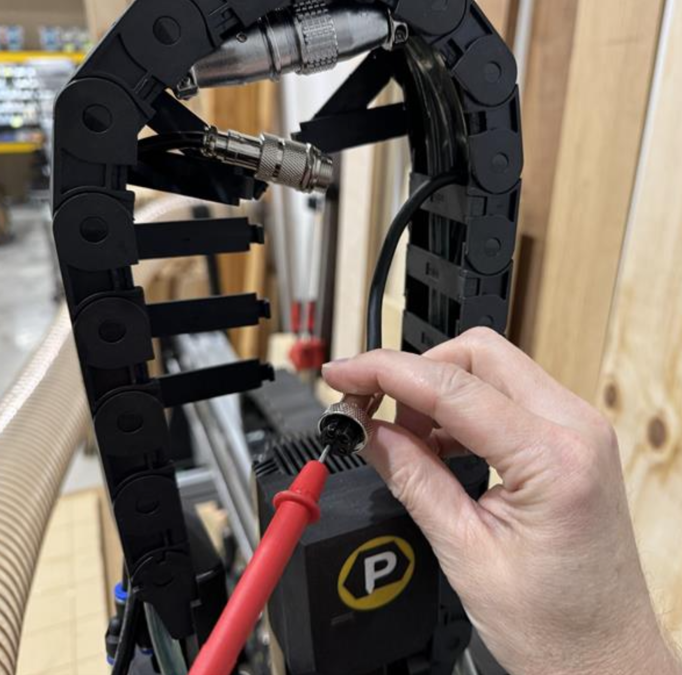
With the machine powered off and the PE powered off, disconnect or access the motor-side sensor connector.
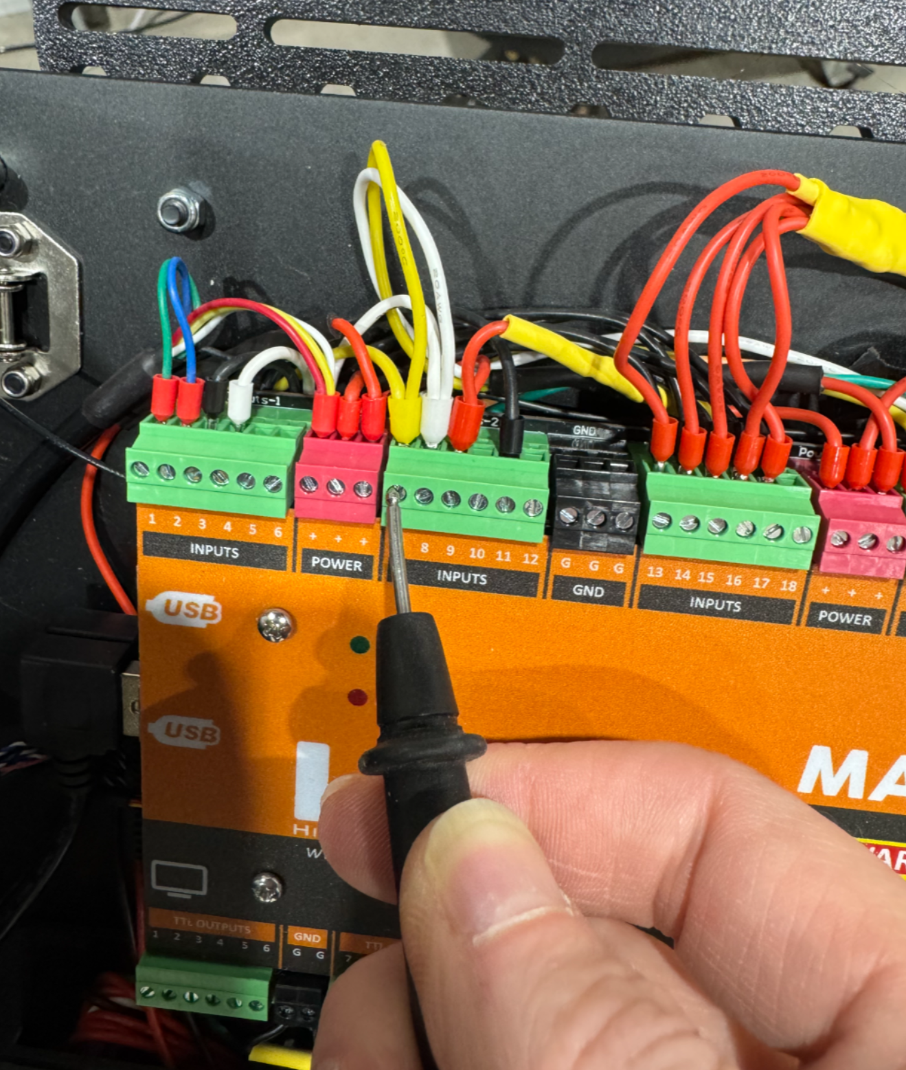
You will be checking the continuity between the motor-side GX16 connector pins and the corresponding G3 controller input terminals.
Pin mapping
| Motor-side GX16 pin | G3 controller input |
|---|---|
| Pin 1 | Input 8 |
| Pin 2 | Input 7 |
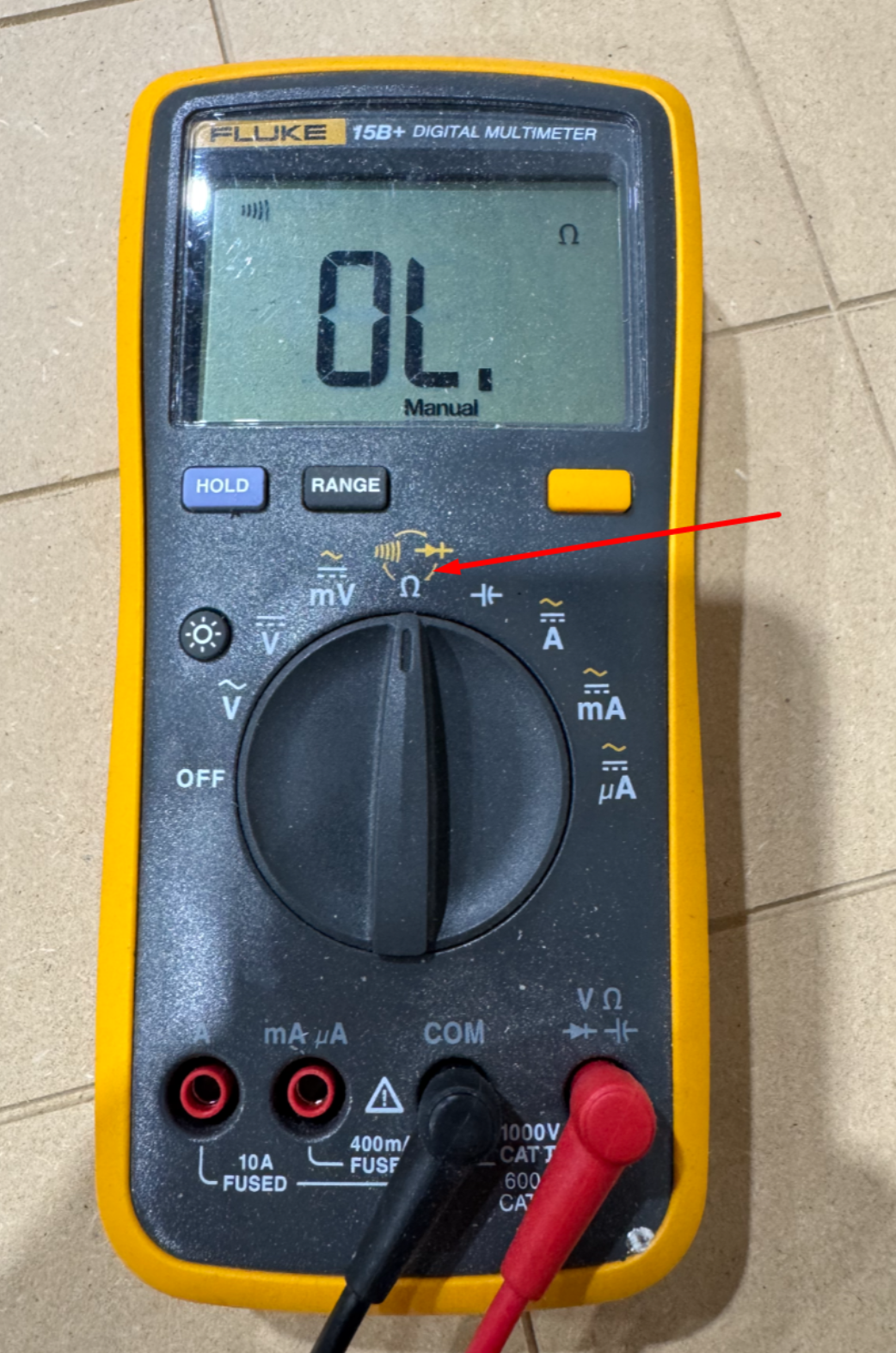
Using your multimeter in continuity mode, check the following:
- GX16 Pin 1 → G3 Input 8
- GX16 Pin 2 → G3 Input 7
There should be a good, clear continuity signal between each connector pin and its matching G3 input.
Expected result
You should hear a solid continuity tone or see a very low resistance reading on the multimeter.
If continuity is poor, intermittent, or missing, inspect the following:
- Loose connector pins
- Damaged cable
- Incorrect wiring
- Loose G3 terminal screws
- Broken wire inside the drag chain
- Incorrect input assignment at the controller
Step 2: Check PE sensor power at the GX16 connector
Next, turn on the PE only.
Do not turn on the machine.
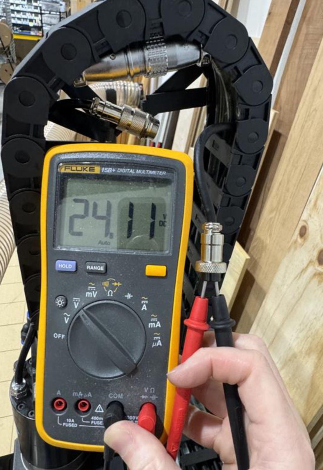
With PE power on, check the voltage coming through the GX16 connector.
Measure voltage across:
- GX12 Pin 3
- GX12 Pin 4
Expected result
The multimeter should show approximately 24V DC.
In the example shown, the meter reads about 24.11V DC, which confirms that the PE is supplying power to the sensor circuits.
What this test confirms
This is the fastest and easiest way to validate two important parts of the ATC sensor circuit:
- The PE is supplying power to the sensors.
- The motor sensor signals are able to travel from the motor-side connector all the way back to the G3 controller inputs.
If both tests pass, the wiring path and PE sensor power are likely good. At that point, continue troubleshooting the ATC sensor behavior, sensor alignment, Masso input status, or sensor configuration.
If either test fails, resolve the wiring or power issue before continuing with ATC troubleshooting.

