


The ATC may seem complex on the surface, but it really does boil down to a sequence of events and each action taken if the expected result is not met than the automatic tool changing will error.
Tool Changer Logic
It is important to first understand what that sequence of events are and the expected results. This will help you identify exactly what the problem you're experiencing is caused by.
When a tool changing command is received... the following events occur.
- Spindle turns OFF (if it was running) and waits for the Spin Down Delay (typically 6sec or so)
- Masso checks to see if the current tool loaded is assigned to a slot (as configured on the F4 Tools screen)
- Masso then checks if the requested tool is assigned to a slot (as configured on the F4 Tools screen)
- Z axis moves to the homing position (typically all the way up)
- X and Y axes move to the tool unload position (this is the position of the current tool loaded so it can drop it off)
- Z axis moves down to the tool unload position
- Chuck Clamp (Output 7) goes HIGH to unclamp the tool
- Waits up to 6 seconds for Draw-Bar sensor to go HIGH (Input 7)
- Tool-Present (Input 8) should then go LOW indicating the tool is no longer in the motor.
- If it does not change from HIGH to LOW, a “Tool Error” alarm is triggered indicating a tool is stuck
- Z axis moves up to clearance position (air will still be blasting out the DUST ports)
- X and Y axes move to the new tool position
- Z axis moves down to the tool load position
- Chuck Clamp (Output 7) goes LOW to clamp the tool
- Draw-Bar sensor (Input 7) should go LOW indicating the Draw-bar is closed and has clamped the tool
- Waits up to 6 seconds for Draw-Bar sensor to go LOW (Input 7)
- Tool-Present (Input 8) sensor must go HIGH indicating the new tool is in the motor.
- If it does not change from LOW to HIGH, a “Tool Error” alarm is triggered indicating no tool is detected
- Z axis moves up to clearance position (air will no longer be blasting out the DUST ports)
- X and Y Axes moves to clear the tool
- Carve continues
Please pay very close attention to these sequence of events and if you need help please indicate how far your tool-change operation made it before erroring.
Basic Troubleshooting
What you need to do when troubleshooting any ATC alarms is to go back to the very basics. IE: Manually Validate the Input sensors using the MTC button.
MTC Button Troubleshooting
Check the assignment of your input sensors on the Setup page.
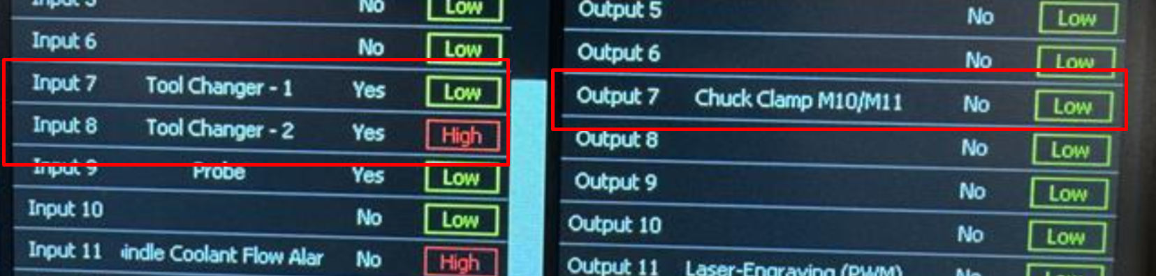
Input 7 should be assigned to "ToolChanger - 1" and inverted. Also it should show as LOW
Input 8 should be assigned to "ToolChanger - 2" and also inverted. IF there is a tool IN the motor right now, it should be HIGH... otherwise no-tool = LOW.
For good measure... your Output 7 should be assigned to "Chuck Clamp M10/M11" and it should not be inverted.
Next... Verify the sensors work properly... place something under the motor to "catch" the tool if it falls out. You don't want to damage the tool holder or your bit.
Verifying Input 7
Push and hold the physical MTC button provided with your ATC System. Don't let go of the button (IE: don't "click" the button)... it's not electrical it's pneumatic which means the system requires time to pressurize and transition from one state to another.
What we expect to happen is your Input 7 should change from LOW to HIGH... and it should stay HIGH the entire time the button is pushed.
Let go of the button and the input should change again... from HIGH to LOW indicating the draw bar is closed.
If the sensor DOES NOT change as expected... that's your problem... and that is what needs to be solved.
Verifying Input 8
This one is simple... Is there a tool in the motor right now?
If no... than Input 8 should be LOW.
If yes... than Input 8 should be HIGH.
Confirm sensor functionality by inserting and removing a tool... checking the sensor state each time.
If the sensor DOES NOT change as expected... that's your problem... and that is what needs to be solved.
Verifying Output 7
On the F2/MDI dialog screen is a virtual MTC button. This is directly linked to Output 7 and will allow you to open the draw-bar by pushing and holding the button for 3seconds.
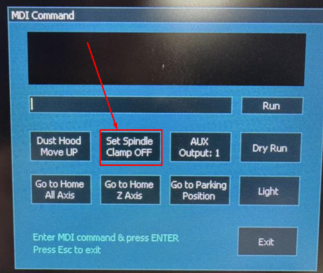
Again make sure something is ready to catch the tool if you have one currently in your motor... then push and hold the "Set Spindle Clamp OFF" button for 3seconds.
The expectation is the air should trigger and open the draw-bar as well as spit air out the dust ports of the motor.
Removing your finger and the dialog will look like this:
Note that the air is still flowing at this point... that is expected, please allow it to continue...
Switch to the F1 setup screen and you should see your Output 8 is now HIGH

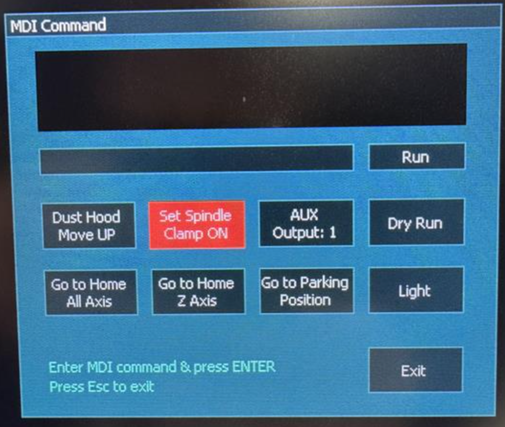
Return to the F2/Program&MDI screen and tap the red "Set Spindle Clamp ON" button again to turn it off.
And return to the F1/Setup screen to verify Output 7 has returned to LOW:

Most Causes of Alarms
If you have verified your inputs and outputs are correctly configured.... yet still you are not getting the expected behaviors... you may have something wrong with your wiring or PE.
This is a good time to reach out to us via [email protected] and let us know where exactly your troubleshooting failed as it is related to the above information.
Advanced Sensor Signal Path Troubleshooting
Note: Fastest way to verify the following is by following this article: https://support.pwncnc.com/kb/article/707-atc-troubleshooting-verifying-motor-sensor-wiring-and-pe-sensor-power/
If your MTC checks or tool-change attempts are still failing because the ATC sensors are not changing state correctly, the next step is to isolate whether the problem is in the motor sensors, the wiring path, the PE, or the Masso inputs.
When not to continue with MDI testing
If the Draw-Bar and Tool-Present inputs are not behaving correctly, additional MDI commands will not provide useful results. Those commands depend on valid sensor feedback. In that situation, stop testing commands and trace the sensor signal path instead.
Sensor signal path overview
The motor sensor cable uses the smaller GX16 connector at the motor.
That cable runs through the drag chains to the PE and plugs into the side of the PE at the 4-pin connector labeled MTR.
These sensors are the same general type as the machine homing sensors and use:
- 24V power
- Ground
- Signal
For the 4-pin MTR connection:
- Pins 1 and 2 carry the two sensor signals
- Pins 3 and 4 provide 24V power and ground
The PE power supply provides sensor power and ground, while the two signal wires are passed into the CTRL cable that exits through the ATC inlet and goes to the Masso G3.
What to verify first
Before going deeper, verify the ATC inlet wiring into the Masso G3 is correct.
https://support.pwncnc.com/kb/article/286-wiring-the-atc-control-inlet-to-masso-g3/
Also confirm:
- the Yellow and White sensor wires are landed on the expected G3 inputs
- the assigned Masso inputs are still configured correctly on the setup screen
- the ATC inlet wiring matches the documented pinout exactly
If you are requesting support, clear photos of the ATC inlet wiring at the controller are very helpful.
Continuity test recommendation
With power off, check continuity between:
- the motor-side GX16 connector
- the Yellow and White wires of the ATC inlet cable
This is one of the fastest ways to determine whether the wiring path through the drag chains and PE is intact.
Results:
- If continuity fails, focus on the cable path, connectors, or PE pass-through
- If continuity passes, the remaining likely causes are the Masso inputs or the motor’s internal sensors
Testing alternate Masso inputs
If you suspect a controller input issue, move the Yellow and White sensor wires from Inputs 7 and 8 to other unused inputs on the G3 for testing.
If you do this, you must also reassign those inputs in the Masso setup screen before testing again.
How to interpret the likely failure point
If both sensors are not behaving correctly at the controller, the most likely causes are:
- A bad signal path somewhere between the motor and the G3
- A bad G3 input
- A failed internal motor sensor
In most cases, a signal path issue is more likely than both motor sensors failing at the same time.
Important note about the NPN sensors
These sensors are NPN, so they rely on the power jumper associated with the Yellow and White signal wires.
If Inputs 7 and 8 are configured as inverted and are showing LOW in their resting state, that usually indicates the power jumper is present and wired correctly.
That means the issue is more likely to be one of the following:
- the signal path is interrupted
- the G3 input is not receiving the signal properly
- the motor sensors are not switching as expected
Safety / service note
If testing ultimately points to failed internal motor sensors, do not open the motor. There are no user-serviceable parts inside.

