


Now that your spindle kit is physically installed and the high-power wiring is complete, it is time for the next step: learning how to operate your spindle in manual mode.
Manual mode is the simplest way to verify that your spindle kit is installed correctly and working as expected. In this phase, the VFD controls the spindle directly using its built-in keypad. You are not connecting automatic controller control yet. That comes later, in a separate article, after you have confirmed that the spindle powers on, starts, stops, and responds correctly to speed changes in manual mode. This step-by-step approach makes the installation process easier to understand and gives you another small win before moving on to the more advanced automatic control setup. This sequencing aligns with the spindle kit manual, which separates manual mode operation from automatic mode and uses the keypad as the primary method for manual spindle control.
What manual mode means
In manual mode, the VFD itself is in charge of spindle operation. That means:
-
you plug the VFD into AC power,
-
use the keypad to start and stop the spindle,
-
and use the dial to adjust spindle speed.
This is the minimum operational state of the spindle kit as shipped. It allows you to confirm that everything is installed properly before introducing controller wiring, controller settings, and automatic spindle commands. The manual notes that controller-based operation is a separate stage and requires different settings depending on the CNC controller.
Before you begin
Before plugging your VFD into an AC Power outlet, make sure:
-
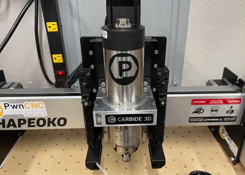
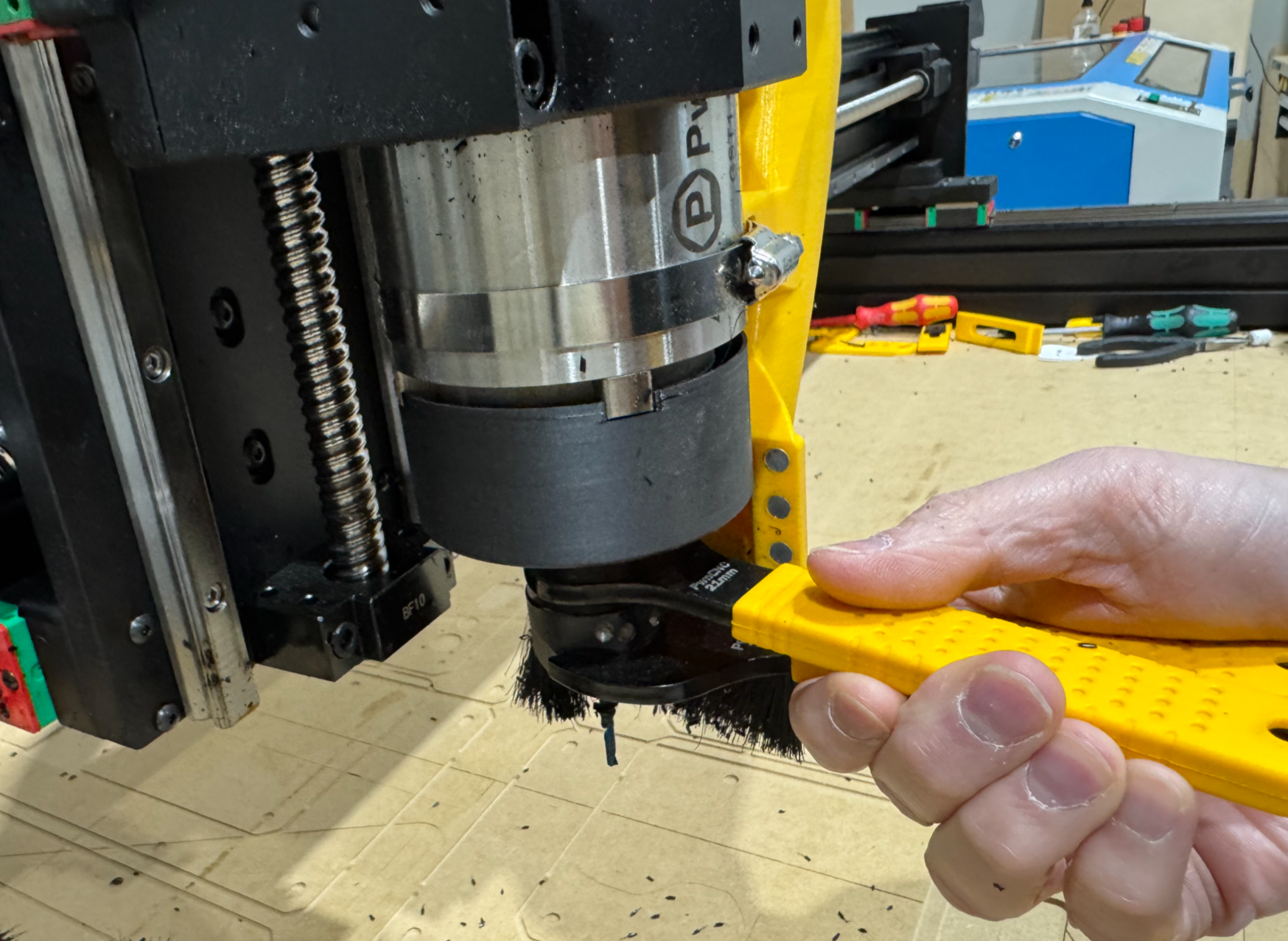
the spindle motor is fully mounted into your CNC machine,
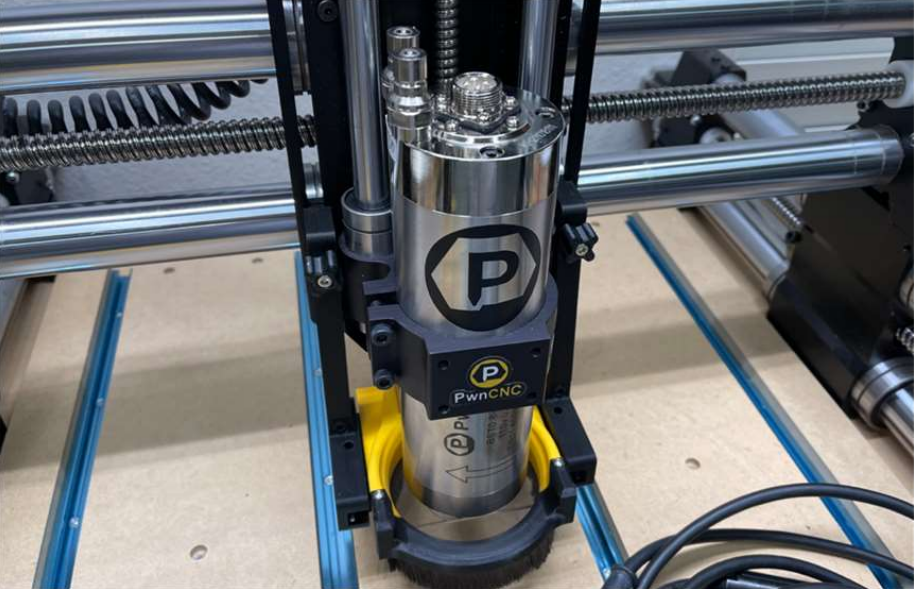
-
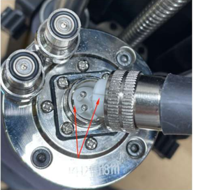
the spindle cable is connected to the VFD and attached to the top of your spindle motor,
-
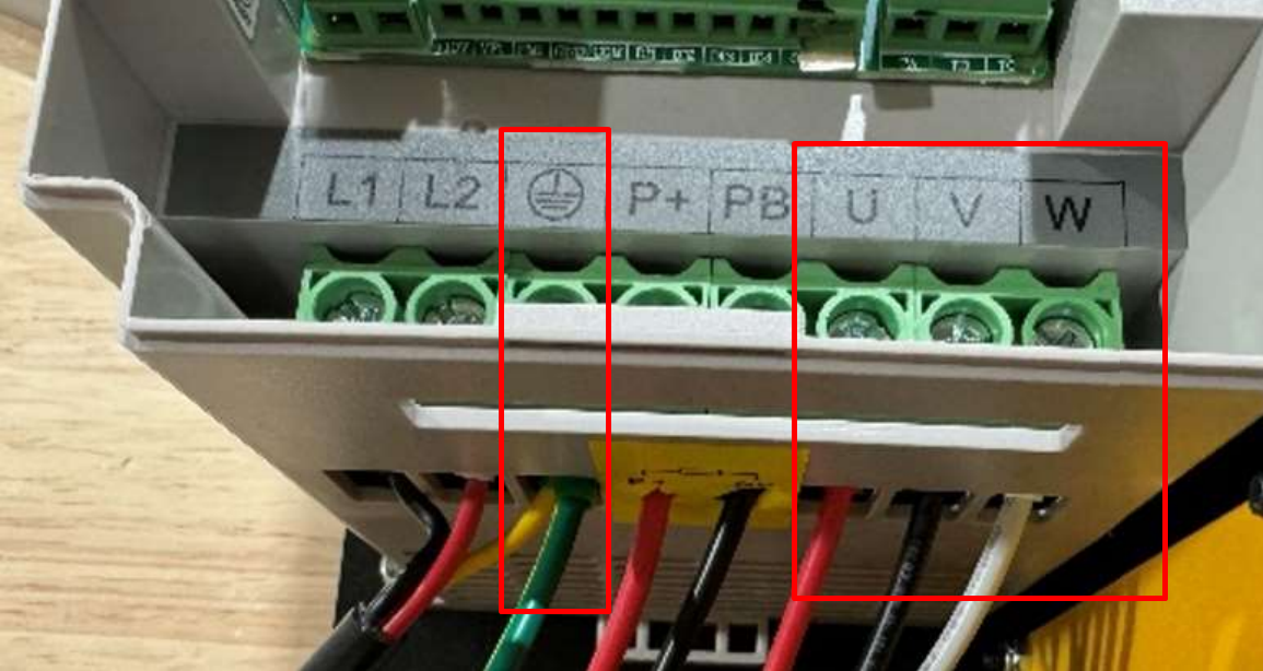
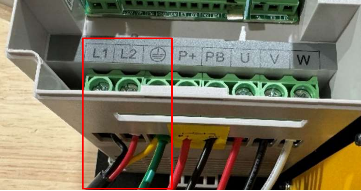
the AC power cord is wired correctly to the VFD,
-
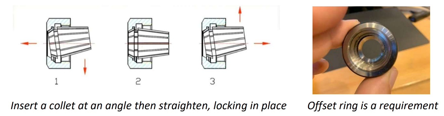
and a bit is installed securely before running the spindle.
-
if water-cooled, your coolant setup is ready
The spindle kit manual specifically recommends securing a bit in the collet before starting the VFD, and using the included two-wrench method for tightening.
Smaller wrench attaches to the motor shaft while the larger wrench attaches to the collet nut.
Powering on the VFD
Plug the VFD power cord into the correct AC outlet for your spindle kit. (110v vs 220v: https://support.pwncnc.com/kb/article/641-power-requirements-110v-220v/)
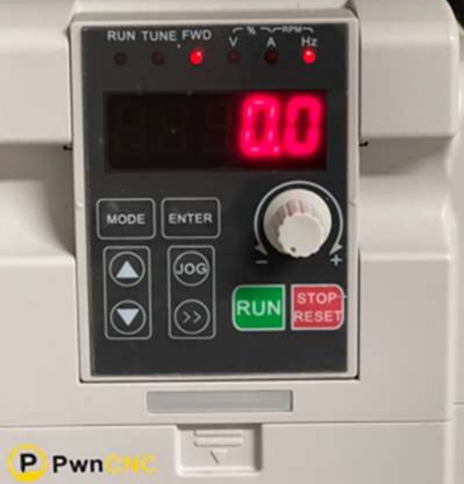
Once the VFD is powered, the keypad should light up with red letters or numbers. In manual standby mode, the display should be blinking. Blinking indicates that the VFD is powered on, but the spindle is currently stopped.
If the keypad does not light up, stop here and re-check your incoming AC power and wiring before continuing.
Starting the spindle
To start the spindle in manual mode:
-
Confirm the keypad display is blinking.
-
Turn the speed dial all the way counter-clockwise first - this is '0' RPMs setting.
-
Press the green RUN button.
-
The display should change from blinking to solid, indicating the spindle is now running.
-
Slowly turn the dial clockwise to increase spindle speed.
The green RUN button and the dial are the basic controls for manual operation. It also recommends starting from a low setting, then increasing speed gradually. The keypad's dial, or potentiometer, regulates frequency and that the FWD LED above the numbers is on when the inverter is in run status.
Stopping the spindle
To stop the spindle:
-
Press the red STOP/RESET button.
-
Watch the display as the spindle slows down.
-
Once the spindle has stopped, the display should return to blinking standby mode.
Stopping the spindle is as simple as pressing the red button, and advises users to wait until the display shows stopped status before reaching near the bit area.
Understanding the keypad
For many customers, this may be the first time using a VFD, so here is a simple overview of what the keypad is doing.
The keypad gives you two important kinds of feedback:
-
Run status
-
What value is currently being displayed
The indicator LEDs across the top show operating status and units. The FWD LED indicates the inverter is running forward. Other indicators show whether the displayed value is voltage, current, frequency in Hz, or rotational speed in RPM. The keypad also includes the RUN button ![]() , STOP/RESET button
, STOP/RESET button ![]() , a dial for speed adjustment
, a dial for speed adjustment  , and a right-arrow style key used to scroll through display values
  .
.
Blinking vs solid display
A simple way to understand the VFD is this:
-
Blinking display = powered on, stopped, standby mode
-
Solid display = spindle is actively running
What the numbers mean
When the VFD is blinking, it will most commonly be showing the current speed setting in Hz, which is the frequency the VFD will send to the spindle when started. The VFD’s base operation is frequency control in Hz, and that higher Hz means higher motor speed. It also notes that PwnCNC programmed the VFD so the display when running can show equivalent RPM values as well.
When the spindle is running, the display will typically show RPM, since that is more intuitive for most users. If needed, the double right arrow button can be pressed to cycle through available display values, including Hz or RPM while running.
Simple first test
A good first manual mode test is:
-
Power on the VFD and confirm the display is blinking.
-
Turn the dial fully counterclockwise.
-
Press RUN.
-
Slowly turn the dial clockwise until the spindle begins spinning.
-
Confirm the display becomes solid while running.
-
Press STOP.
-
Confirm the display returns to blinking once the spindle stops.
A note about Hz and RPM
VFDs naturally control motors by output frequency, not directly by RPM. That is why Hz is a normal thing to see on the keypad. PwnCNC has programmed the VFD so customers can also view RPM, which is usually easier to understand during spindle operation. For reference our spindle motors are typically 0-400Hz or 24,000 RPM... thus a value of 200 Hz corresponds to 12,000 RPM on this programmed setup, and that the display can be cycled between values using the keypad.
Warm-up reminder
We recommend a spindle warm-up procedure, especially after long downtime or in cold conditions. We suggest beginning at a lower RPM, then gradually stepping up speed over time to allow the spindle bearings and lubricant to come up to operating condition.
What comes next
Once you have confirmed that:
-
the VFD powers up,
-
the keypad blinks in standby,
-
the spindle starts when you press RUN,
-
the display turns solid while running,
-
the dial changes spindle speed,
-
and STOP returns the unit to blinking standby,
then your spindle kit is successfully operating in manual mode.
You can now treat the spindle exactly like you would a palm router, if you were using one before. This is how you can run PwnCNC Spindles and VFDs on router table setups or in manual mode on CNC machines.
The next phase is automatic mode, where your CNC controller takes over spindle start, stop, and speed control. That step requires additional wiring and settings, so it is covered separately in the next article.

