


Spindle Kit Start Here: Phase 1, Manual Operation First
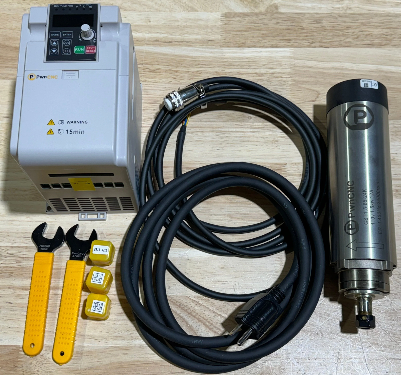
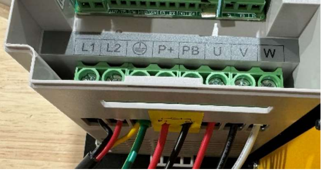
Welcome to the start of your spindle kit installation. To make this process easier and more approachable, we break the spindle kit setup into two phases. In Phase 1, you will complete the minimum wiring needed to power and run the spindle in manual mode, directly from the VFD. This includes connecting the AC power cord to the VFD’s L1, L2, and Ground terminals, and connecting the spindle motor power cable to the U, V, W, and Ground terminals. By focusing on these core power connections first, you can achieve an important early win: getting your spindle installed, powered, and running as shipped, without adding the extra complexity of controller integration right away.
Once your spindle kit is physically installed and operating in manual mode, you can move on to Phase 3, which is automatic mode. Automatic mode allows your CNC controller to command the VFD for spindle start, stop, and speed control, but it requires additional wiring, settings, and controller-specific setup. Because that process is more advanced and varies depending on your controller, it is covered in a separate knowledge base article. For now, this page is focused only on the essential high-power wiring needed to get your spindle kit up and running safely and successfully.
What this page covers
This article will walk you through the minimum required high-power wiring for manual spindle operation:
-
AC input power to the VFD: (cable that runs between your AC outlet and the VFD)
-
L1 - Black wire from your AC Power Cord
-
L2 - White or Red wire from your AC Power Cord
-
Ground - Yellow and/or Green wire from your AC Power Cord
-
-
Spindle motor output from the VFD: (cable that runs between the VFD and Spindle Motor)
-
U - Red wire from your Spindle Motor Cord
-
V - Black wire from your Spindle Motor Cord
-
W - White wire from your Spindle Motor Cord
-
Ground - Yellow and/or Green wire from your Spindle Motor Cord
-
Shield Drain - unshielded silver mesh twisted into a single wire. This drains any EMI picked up or produced by the Spindle Cable. Attach this to a wire you have running to earth-ground.
-
Note that the AC Ground and Spindle Ground are the same and wire into the same terminal on the VFD.
Next -> Phase 2 - Manual Mode Operation

