


Read This Before Wiring Anything
This article explains the rules, philosophy, and constraints behind wiring your PwnCNC Conversion Kit.
Before you land a single ferrule or power anything on, read this once.
Most wiring issues we see are not mistakes in following diagrams, they are misunderstandings of why things are wired the way they are.
What This Article Is (and Is Not)
This article:
-
Explains grounding, shielding, and power flow concepts
-
Sets hard boundaries on what is safe and what is not
-
Helps you avoid damage before it happens
This article does not:
-
Replace the Core or Advanced wiring guides
-
Walk pin-by-pin through connections
-
Cover machine-specific routing or mounting
Those details live in the dedicated wiring articles linked at the end.
Big Picture: How Power and Signals Flow
Your conversion kit has three distinct electrical domains:
-
High-current motor power (36V DC)
-
Logic and control power (24V DC)
-
Low-level signals (step, direction, alarms, probes, PWM)
Keeping these domains separated, shielded, and grounded correctly is the entire game.
Most problems happen when these boundaries are violated.
Star Grounding: One Ground, One Reference
Your conversion kit is designed around a star grounding concept.
That means:
-
All grounds reference a single earth point
-
Grounds do not daisy-chain between devices
-
Shield drains terminate at one intentional location
Why this matters:
-
Prevents ground loops
-
Prevents static discharge paths through electronics
-
Prevents false stepper alarms and proximity triggers
If your machine has a grounding block or earth stud, that is typically the correct place to bond:
-
Stepper cable shield drains
-
VFD ground
-
Machine frame ground
Shield Drain Philosophy (Very Important)
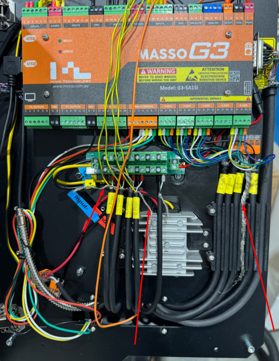
Your stepper cables are physically shielded, but shielding only works when it is terminated correctly.
Key rules:
-
Shield drains must be tied to ground at one end only
-
Never leave shields floating
-
Never connect shield drains to signal inputs
A floating shield can be worse than no shield at all, especially when using a shop vac or dust collection.
Why Ferrules Matter (And Why We Use Them)
Ferrules are not cosmetic. They:
-
Prevent strand splay
-
Improve long-term connection reliability
-
Reduce heat buildup at terminals
-
Make future service safer and cleaner
We intentionally use ferrules and phoenix connectors to:
-
Keep costs down
-
Make repairs easier
-
Avoid proprietary harnesses
If you shorten or re-terminate wires, always reinstall ferrules. Simple ferrule-kits are available on amazon for a little as $15.
What Never Goes Between Controller and Motor
This is a hard rule set.
Never place anything between the controller and a stepper motor except the supplied cable.
Do not add:
-
Relays
-
Switches
-
Terminal blocks
-
Connectors
-
Extension cables
Breaking the motor circuit under power can permanently damage drivers and motors.
Power Comes Last, Not First
Do not apply power until:
-
All motors are mounted and aligned
-
All cables are fully seated
-
Grounds are bonded
-
Shields are terminated
-
No loose ferrules exist
Powering too early is how small wiring mistakes become expensive ones.
Core vs Advanced: Wiring Philosophy Differences
Conversion Kit Core
-
Direct wiring into the Masso controller
-
Fewer prewired accessories
-
More hands-on ferrule work by design
Conversion Kit Advanced
-
Prewired inlet panel for accessories
-
Cleaner expansion paths for probes, spindle, ATC, rotary
-
Same grounding and shielding rules apply
The electrical principles are identical. Only convenience differs.
When to Pause and Ask
Stop and contact support if:
-
You are unsure where a shield drain belongs
-
You are tempted to “just try it powered on”
-
A motor alarms immediately on enable
-
Something feels forced or unclear
Pausing early saves hours later.
Next: Detailed Wiring Guides
Once you understand the rules above, continue here:
These guides assume you’ve read this overview.

