If you're controller requires a digital converter to convert the Digital PWM signal it produces into an Analog PWM signal that our VFD recognizes, here are some details that are useful to you.
Wiring into VFD
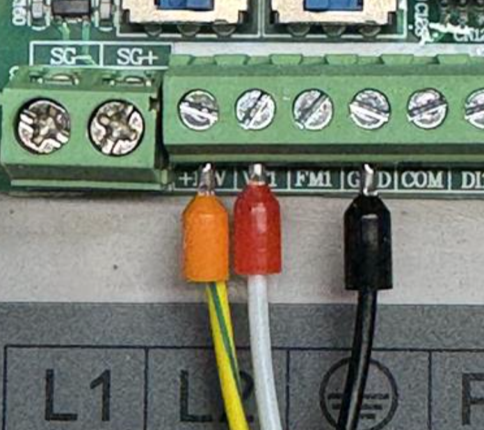
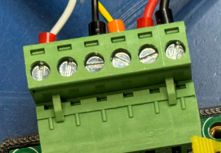
The digital converter requires power to operate so the VFD side involves three wires: Orange, Red, and Black.

Orange goes into "+10V"
Red into "VF1"
Black into "GND"
Wiring Digital Converter
The digital converter itself will come prewired so you don't have to worry about that.

Wiring your Controller
Two wires coming out of the digital converter will be Red and Black.
These are short wires as the converter itself should sit close to the controller's PWM input.
Red being the actual PWM signal
Black being the Ground

Achieving the perfect Voltage to RPMs
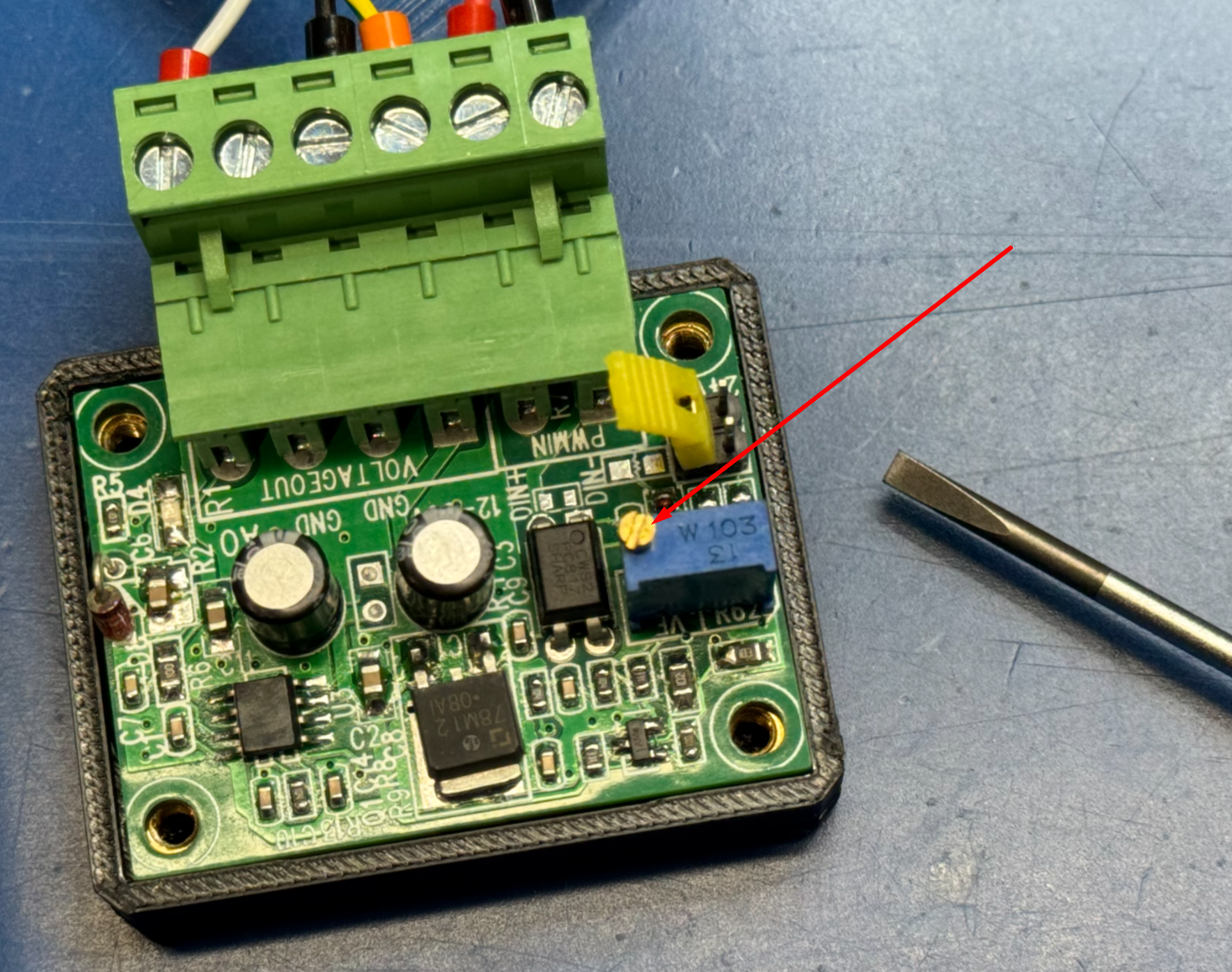
If you are not achieving the correct RPM's, it may be that you'll need to tweak the converter for the perfect digital to analog conversion. This can be done by opening the converters 3d printed enclosure and turning the brass screw on top of the little blue box mounted to the circuit board:

Twist the screw clockwise or counter-clockwise until you see the RPMs on the VFD's screen change. If the RPMs are going further away from the controller commanded RPMs, then twist the screw the opposite direction.
Twist until the RPMs on the VFD's screen matches what is displayed on your controller.
It is expected that a digital converter will have a variance of upwards of 10-15% compared to what the controller is telling the VFD to go.


